
General
-
What do I have to do to get remote access to my Lupus device?
-
P2P connection
All current LUPUS devices support P2P connection. A port forwarding or DDNS address is no longer necessary if you use our app for the remote access.
Below the old and now longer necessary manuals if you still want to use port forwarding and DDNS:
How can I access my router? (Due to P2P now longer necessary)
In order to gain access to your devices via the internet, you have to set up a port forwarding in your router. In case you do not know the IP address of your router, you can find in the following way:
Windows PC MAC - Start the command interface
Type in "cmd" in the start menu (without quotation marks)- Type in “ipconfig”
- Standardgateway is the IP address of your router
- Open the system settings
- Click on network
- Select your current network connection (Ethernet or WLAN)
- The tab TCP/IP lists the IP address of your router
How do I set up a port forwarding in my router? (Due to P2P now longer necessary)
*Currently, there are only German manual availableHow do I access my device? (Due to P2P now longer necessary)
After you have created a port forwarding as described in the manuals above, you can access your device by typing in the following address in your web browser:
https://YourName.lupus-ddns.de:ExternalPortThe real command would look similar to the following:
https://demoxt2.lupus-ddns.de:53080
http://demoxt1.lupus-ddns.de:10000Which port do I need to forward in my router? (Due to P2P now longer necessary)
In the following table, the internal ports of our devices are listed:
Device Internal port XT1 / XT2 80 XT2 Plus 443 (SSL encrypted - recommended) or 80 (not encrypted) LE 9xx cameras 80 LE 200 80 (older firmware versions 88) LE 201 / LE 203 TCP 80, TCP 37777, TCP 1935, and UDP 37778 (see FAQ LUPUSTEC → General → "Required port forwarding for an access via internet") Recorder HDTV / NVR / HD-SDI TCP 80 and TCP 37777 and UDP 37778 (see FAQ LUPUSTEC → General → "Required port forwarding for an access via internet") Change the standard password of any device you allows to be accessed from the internet!
- Start the command interface
-
How do I activate the Lupus ddns service in my Fritz!Box?
-
In the settings of you Fritz!Box, you need to open the menu "Internet" → Permit Access" → "Dynamic DNS" and insert the following information:
As "Dynamic DNS Provider" please select "Custom."
Update-URL (do not change the following command):
my.lupus-ddns.de/nic/update?hostname=<domain>Domainname:
Please insert your lupus ddns name – e.g. yourname.lupus-ddns.deUsername:
Please insert the user name of your Lupus ddns accountPassword:
Please insert the password of your Lupus ddns account
-
Which App can I use?
-
Device Android iOS XT1 / XT1 Plus / XT2 (Plus) /XT3 LUPUS LUPUS LUPUS LE2xx LUPUS LUPUS HDTV / HD-SDI / NVR Rekorder LUPUS LUPUS Netzwerkkameras (LE 9xx) LUPUS LUPUS LUPUSNET HD - LE200 LUPUS LUPUS Ältere IP Rekorder (LE 904 / 909) ip motion lite LUPUSNET HD Ältere analog Rekorder (LE800 / + / D1) SoCatch SoCatch Please note that we are not liable for any problems that might occur while using Apps that were note developed by us.
-
Why is the email notification not working?
-
General
Please make sure that your IP settings are correct. If you are in doubt, please set the alarm panel to DHCP.
Some routers have a list of secure e-mail servers (e.g. speedport of the German Telekom) that might block some e-mail providers if it is active. If your router has a similar function, please deactivate it.Which e-mail providers work with my XT?
We tested selected popular and free e-mail providers. If a provider is not listed, it only means that we did not test this provider – it does not mean that the provider does not work.
Provider XT1 XT1 Plus / XT2 (Plus) / XT3 / XT4 LE201/202/203/204 LE 9xx LUPUSTEC HDTV & NVR recorder Gmail +
smtp.gmail.com
(TLS Port 587) - allow access of less secure apps+
smtp.gmail.com
(TLS Port 587) - allow access of less secure apps+
smtp.gmail.com
(TLS Port 587) - allow access of less secure apps
Attachment: Yes+
smtp.gmail.com
(TLS Port 587) - allow access of less secure apps
Attachment: Yes+
smtp.gmail.com
(TLS Port 587) - allow access of less secure apps
Attachment: YesYahoo +
smtp.mail.yahoo.com
(SSL Port 465) - Allow apps that use less secure log in+
smtp.mail.yahoo.com
(SSL Port 465) - Allow apps that use less secure log in+
smtp.mail.yahoo.com
(SSL Port 465) - Allow apps that use less secure log in
Attachment: Yes+
smtp.mail.yahoo.com
(SSL Port 465) - Allow apps that use less secure log in
Attachment: Yes+
smtp.mail.yahoo.com
(SSL Port 465) - Allow apps that use less secure log in
Attachment: YesFreenet - +
mx.freenet.de
smtp e-mail sending needs to be enabled (protocol disabled)
Port 465 or 587+
mx.freenet.de
smtp e-mail sending needs to be enabled (protocol disabled)
Port 587 (TLS)
Attachment: Yes+
mx.freenet.de
smtp e-mail sending needs to be enabled (protocol disabled)
Port 587 (TLS)
Attachment: Yes+
mx.freenet.de
smtp e-mail sending needs to be enabled (protocol disabled)
Port 587 (TLS)
Attachment: YesMail.de - +
smtp.mail.de
Port: 465 SSL+ / -
smtp.mail.de
Port: 465 SSL
Attachment: No+
smtp.mail.de
Port: 465 SSL
Attachment: Yes+
smtp.mail.de
Port: 465 SSL
Attachment: YesGMX - +
mail.gmx.net
(TLS Port 587) - allow e-mails to be send by third party devices+
mail.gmx.net
(TLS Port 587) - allow e-mails to be send by third party devices
Attachment: Yes- +
mail.gmx.net
(TLS Port 587) - allow e-mails to be send by third party devices
Attachment: YesWeb.de - +
smtp.web.de
(TLS Port 587) - allow e-mails to be send by third party devices+
smtp.web.de
(TLS Port 587) - allow e-mails to be send by third party devices
Attachment: Yes- +
mail.gmx.net
(TLS Port 587) - allow e-mails to be send by third party devices
Attachment: YesOutlook / Hotmail - - - - - Telekom - +
securesmtp.t-online.de
(SSL Port 465) - You need to set a separate e-mail password
Not recommended for security reasons: Telekom does only allow you to send 100 mails per day (and not more than 1000 per month).+
securesmtp.t-online.de
(SSL Port 465) - You need to set a separate e-mail password
Not recommended for security reasons: Telekom does only allow you to send 100 mails per day (and not more than 1000 per month).
Attachment: Yes- +
securesmtp.t-online.de
(SSL Port 465) - You need to set a separate e-mail password
Not recommended for security reasons: Telekom does only allow you to send 100 mails per day (and not more than 1000 per month).
Attachment: YesWeb.de and gmx.de are owned by 1&1. Hence, 1&1 should work accordingly with the corresponding 1&1 smtp server.
Outh owns Yahoo and AOL. Hence, AOL should work like Yahoo with the corresponding AOL smtp server.
-
How do I set up the IP adress of my device via the IP-Finder?
-
How do I set up the network address of my XT or camera via the LUPUS IP finder?
The XT1, as well as, our network cameras of the 9xx series are shipped with a static IP address (192.168.1.200). In order to access the devices, the IP address needs to be adapted to your local area network. Otherwise, the device cannot communicate with your network.
In order to set the IP address, it is easiest to use our IP finder (Download: Windows / MAC). The IP finder checks your complete network for devices of LUPUS-Electronics, displays there current IP address, and allows you to change these settings.
You can choose between DHCP and a static IP address. The advantages of using DHCP or a static IP address, as well as, an explanation of the settings for a static IP address can be found in the FAQ "General" → "IP address configuration - DHCP or static IP address."After you have set a correct IP address or switched to DHCP, you can access your device in your standard browser by double clicking on it directly in the IP finder.
Cameras, which are already set to DHCP by default (e.g. LE 200 / LE 201), can also be accessed directly via the IP finder by simply double clicking on the camera.However, it is not possible to set the IP address of our recorders in the IP finder. To set up the IP address of your recorder, please refer to the FAQ "LUPUSTEC" → "General" → "Why can't I access my recorder via web browser / SmartVision software?".
-
IP address configuration - DHCP or static IP address
-
How to correctly set up an IP address
When setting up the IP address of any device, you can choose between DHCP and a static IP address.
DHCP (dynamic host configuration protocol) is a function, by which your XT or camera receives all required IP settings from your router.
- The advantage of DHCP is that all required IP settings are automatically performed by your router. Thus, these information will always be correct. However, to use DHCP your router / server need to support this protocol and it needs to be activated – generally, this function is active in all common routers.
- The disadvantage of DHCP is that your router will reset all IP addresses assigned via DHCP after an adjustable time. Thus, the IP address of you XT or camera can change. Depending on your router, the IP address of a device can also change after the device or your router reboots.
As a result, the remote access via a port forwarding might be inactive if the router changes the IP address of a device, but does not update the IP address in the port forwarding as well.
If you want to use a static IP address, you need to set all IP information manually.
- The advantage of a static IP address is that the IP address of your XT or camera is fixed and will never change. Depending on your router, a static IP address might be required to guarantee a constantly working remote access (you can find more information about port forwarding in the FAQ "General" → "What do I have to do to get remote access of my Lupus device?").
- The disadvantage of a static IP address is that you need to set all IP information manually. The information have to be completely correct and need to fit to the infrastructure of your local area network
- If some of the IP information are incorrect, you might not be able to access your device or some functions of you device might not work correctly. If this is the case, we advise you to check your settings or use DHCP.
How do I assign a static IP address correctly?
If you want to assign a static IP address, you are required to fill in the following IP information:
IP address:
This is the IP address, by which you will access your XT or camera in your local area network. This IP address may only be assigned to a single device and needs to be outside of the IP range of your DHCP server (the DHCP range of your server is set in your router). The first three parts of the IP address have to be identical to the IP address of your router (e.g. 192.168.123.xxx).
Subnet mask:
The subnet mask defines of how many bits the net prefix consists of, thus, defining which IP addresses are assigned and can be accessed in your local area network. You can check for your subnet mask via the command panel (see gateway). In most local area networks with an 192.168.xxx.xxx IP address, the subnet mask is 255.255.255.0
Gateway:
The gateway is the IP address of your router or the device by which your XT or camera communicates with the internet. This IP address can be checked in the following way:
Windows PC MAC - Start the command interface
Type in "cmd" in the start menu (without quotation marks)- Type in “ipconfig”
- Standardgateway is the IP address of your router
- Open the system settings
- Click on network
- Select your current network connection (Ethernet or WLAN)
- The tab TCP/IP lists the IP address of your router
DNS 1:
A domain name server is required for the name resolution of internet addresses, hence for the communication with the internet. In most networks, the IP address of the router can be used. The router will forward the query to suitable domain name servers. As an alternative, you can also define a server manually (e.g. google: 8.8.8.8).
DNS 2:
A domain name server is required for the name resolution of internet addresses, hence for the communication with the internet. In most networks, the IP address of the router can be used. The router will forward the query to suitable domain name servers. As an alternative, you can also define a server manually (e.g. google: 8.8.4.4).
-
Portforwarding with IPv6 (DSLite)
-
P2P connection
All current LUPUS devices support P2P connection. A port forwarding or DDNS address is no longer necessary if you use our app for the remote access.
Why is it not possible to set up a remote access / port forwarding with a IPv6 or an DS-lite tunnel?
Update: If you have a DS-Lite or pure IPv6 internet address, please contact our support team. We can activate a function in your XT (XT1 Plus, XT2 Plus, XT3, XT4) that will allow you to have a remote access to your alarm panel.
It is not possible to access a router that uses an IPv6 address or a DS-lite tunnel as long as the infrastructure of a country is based upon IPv4.
This is true for all devices of all companies (e.g. even a VPN tunnel cannot be created in such a network).An IPv4 is required for a remote access, because this internet protocol is currently, and since the creation of the internet, the standard for the communication in the internet. As soon as the providers have changed their whole infrastructure to IPv6, a remote access via IPv6 is also possible.
Currently, IPv6 has a worldwide coverage approx. 15%. Hence, a router with an IPv6 address or DS-lite tunnel cannot be accessed from the internet, because nearly all devices (e.g. your smartphone) are still using IPv4.
To create a remote access, your smartphone needs to be able to communicate with your router and the router forwards the incoming signals to the device you want to reach in your local area network (e.g. your alarm panel). However, if your router uses an IPv6 address or DS-lite tunnel, your smartphone cannot communicate with your router and, therefore, the router cannot forward the signals.
IPv4 and IPv6 have both advantages and disadvantages.
IPv4 is the standard for the communication in the internet that can handle, both, IPv4 and IPv6 signals. In short, its advantage is that it features a high compatibility. Its disadvantage is the available amount of IP addresses (there are only 4.3 billion addresses available).
The advantage of IPv6 is the incredible amount of available IP addresses (approx. 340 undecillion – a figure with 39 numbers with enough available addresses for 600 trillion devices per mm² of the earth). The disadvantage of IPv6 is that this protocol is not downward compatible to IPv4. Thus, all devices need to use an IPv6 if you want to use this protocol. For this reason, providers are beginning to change the infrastructure of their grids.However, this also leads to problems when you want to remotely access a device. If your provider already supplied you with one of the cheaper IPv6 addresses (they are cheaper because of the sheer amount of addresses), but the infrastructure of the complete internet / telephone network is not yet adapted to IPv6, a remote access cannot be established. As soon as the infrastructure is adapted to IPv6, an IPv6 remote access will be no problem.
To change the IP address of the XT to IPv6 would not solve this problem, since the communication is not possible between your smartphone and your router. Hence, the IP address of the XT is not relevant at this point.
Furthermore, this change could lead to access problems for someone whose router does not support IPv6How can you solve this problem for the time being?
You need to contact your internet provider and tell them that you need an IPv4 address that will allow you to set up a remote access. This is mostly called "dual stack" (not lite!) or bridge mode.
-
How do I access an IPv6-address with my webbrowser?
-
You need to enclose the IPv6-address in square brackets [ ]:
http://[ADDRESS]/
- Example: http://[fe80::20f:dff:fe24:f002]/
-
What to do if my app does not work anymore?
-
If your app does not work anymore, please prepare the following questions in order to help us to solve your problem
- Which device do you want to access (XT1, XT2, XT2 Plus, which recorder, which camera)?
- How do you access the device?
- Local IP or DDNS address?
- WLAN or mobile data?
- If you use WLAN, are you and the device you want to access connected to the same WLAN?
- Do you use a VPN connection or something similar?
- Which cameras are connected to your XT or recorder (manufacturer and model number)?
- Please retrace the steps that lead to the malfunctioning of the app
- Which error message is displayed?
- Does this problem occur on all of your smartphones / tablets / computers or just on this individual one?
- Which version of the app is installed?
- When did you install the last update?
- Did this problem also occur in the older version?
General Operating cost statement
-
Remote radio reading of consumption values
-
Remotely readable meters automatically record consumption data and transmit it digitally to the supplier. This saves time, avoids on-site meter readings and enables accurate, prompt billing. Users gain more transparency about their consumption and can save energy in a more targeted manner. Billing errors are also reduced.
-
How are heating costs calculated?
-
We receive an overview of the heating, ancillary heating and other operating costs from your landlord or property management company (see service charge statement). We first check this data for plausibility. We then divide the total costs of the heating system into heating costs and hot water costs. We form two cost shares from each of these two totals: The basic cost share includes the costs for heat provision and pipe losses. According to the Heating Costs Ordinance, your property management company can set this share at between 30 and 50 percent. It is usually distributed according to the living space, as it is independent of individual heating behavior. The remaining 50 to 70 percent are consumption-based costs. These depend directly on your heating behavior. After the meter has been read, we prepare an overall bill for the property management company and individual bills for all users. You will receive your personal statement from the property management company. Additional apportionable operating costs may also arise, which are regulated in the tenancy agreement and can also be billed.
-
What is necessary to create heating bills with the LUPUS Cloud?
-
To create heating bills with the LUPUS Cloud, you need at least one LUPUS gateway in the building, as well as remotely readable consumption meters in the residential units.
XT Alarm Panels General
-
How to avoid unnecessary alarms?
-
Please note the following points to prevent false alarms
Alarm during the exit delay
If you have set up your XT2 (Plus) to use an exit delay, be aware that all sensors can trigger an alarm during this delay. Even motion detectors which are set to inactive (e.g. in home mode) can trigger an alarm during the exit delay when switching to home mode.
To prevent this, please check to option "Mind the exit delay" in the menu "Sensors" → "List" → "Edit."
Of course, this option should only be enables in sensors which should not trigger an alarm during the exit delay (all sensors you might trigger when leaving the house or during the delay when you switch to home mode).Tampering alarm
A tampering alarm of a sensor can only be triggered by the tampering contact of a sensor. Depending on the type of sensor, this means, that the sensor is not installed correctly or is open / opening.
We recommend to use screws for the installation of every sensor to prevent an accidental triggering of a tampering contact.The PIR motion detector triggered an alarm even if no object was moving.
PIR sensors detect movements via passive infrared. Thus, these motion detectors are triggered by movements of temperature fields. This could be the body temperature of a human being or animal, but also changes in the temperature caused by radiators (also heated floors) or other devices.
We do not recommend to install these PIR devices in rooms with heated floors, directed at huge windows, or at the top of staircases since the warm air that rises to the top of the room can trigger these sensors.
-
Why do I always need two attempts to arm my alarm panel?
-
If you cannot arm the alarm panel on the first attempt (e.g. via remote control or keypad) and you hear to different signal tones, the alarm panel notifies you about a problem. This could be an open door contact, open tampering protection, or a low battery, etc..
You can override this warning and force the arming of the alarm panel by enabling the arm mode again within 10 seconds.
-
Which sensor is compatible with my XT alarm panel?
-
XT sensor compatibility
-
Which batteries do I need?
-
We update this list as regular as possible. However, especially older sensors might use other batteries than the one's listed here.
Please check the batteries that are currently inserted in your sensor to make sure, that you buy the correct battery!If your sensor has a 3V 1/2 AA battery, you can also use a 3v CR2 battery.
-
Which products can be repeated by the wireless repeater (12016)
-
The following procuts can be repeated via our Wireless repeater (12016)
Product Item No. Alarm sensors
Door contact (white) 12002 PIR motion detector 12003 Smoke detector 12004 Water sensor 12007 Medical emergency controller 12009 Glass breaking sensor 12011 Panic button 12015 Heat detector 12018 CO detector 12019 Sensor input 12020 Dual way motion detector 12034 Door contact (brown) 12037 Door contact (anthracite) 12038 Curtain motion detector 12110 360 ° motion detector 12111 Door contact V2 (white) 12113 Door contact V2 (brown) 12114 Door contact V2 (anthracite) 12115 PIR motion detector V2 12116 Smarthome / Home automation
Lockswitch contact 12026 Control units
XT Keypad 12001 Remote control 12008 Tag reader 12028 Outdoor keypad 12070 Control units (requires repeater version 04/17 or later) Keypad V2 12106 Tag reader V2 12107 Remote control V2 12108 Outdoor Keypad V2 12109 Sirens
Indoor siren 12005 Outdoor siren V2 12033 Outdoor siren -
-
Which products can be repeated by the wireless repeater V2 (12122)
-
The following procuts can be repeated via our Wireless repeater V2 (12122)
Product Item No. Alarm sensors
Door contact (white) 12002 PIR motion detector 12003 Smoke detector 12004 Water sensor 12007 Medical emergency controller 12009 Glass breaking sensor 12011 Panic button 12015 Heat detector 12018 CO detector 12019 Sensor input 12020 Dual way motion detector 12034 Door contact (brown) 12037 Door contact (anthracite) 12038 Glass breaking sensor V2 - RF Version 12103 Vibration sensor 12105 Curtain motion detector 12110 360 ° motion detector 12111 Door contact V2 (white) 12113 Door contact V2 (brown) 12114 Door contact V2 (anthracite) 12115 PIR motion detector V2 12116 Smoke detector V2 12117 Emergency button 12123 Sensor input (9 fold) 12125 Smarthome / Home automation
Lockswitch contact 12026 Wireless repeater V2 12122 Control units
XT Keypad 12001 Remote control 12008 Tag reader 12028 Outdoor keypad 12070 Keypad V2 12106 Tag reader V2 12107 Remote control V2 12108 Outdoor Keypad V2 12109 Remote control V3 12118 Sirens
Indoor siren 12005 Outdoor siren V2 12033 Outdoor siren -
-
Which products can be repeated by the wireless repeater Pro (12205)
-
Die Reichweite folgender Produkte können Sie mit dem Funkrepeater Pro (12205) erweitern
Produkt Art.-Nr. Gefahrenmelder
Bewegungsmelder Pro 12201 Outdoor Bewegungsmelder Pro 12202 Fenster-/ Türkontakt Pro (weiss) 12203 Fenster-/ Tür Rahmenontakt Pro 12204
-
Which products can be repeated via our ZigBee repeater?
-
The range of the following products can be expanded by our LUPUS ZigBee repeaters.
Product Item No. Alarm sensors
PIR network camera V2 12041 Water sensor V2 12047 Glass breaking sensor V2 - ZB Version 12103 Smarthome / Home automation
Relay with dimmer V2 12030 Shutter relay 12031 Light switch 12046 Temperature sensor V2 12048 Temperature sensor with display V2 12049 Remote controlled mains socket with power meter and ZigBee repeater 12050 Relay with power meter V2 12051 12 / 24 V relay 12052 Radiator valve thermostat 12053 Scenario switch 12061 Universal IR Controller 12062 Top-Hat relay DIN2 12063 Top-Hat relay DIN3 12064 Light sensor 12065 Electric Meter 12071 Light switch V2 12072 Status Display 12101 Szenario switch V2 12102 Temperature sensor with external probe 12124 1 channel relay with ZigBee repeater 12126 2 channel relay with ZigBee repeater 12127 Shutter relay V2 12128 Radiator valve thermostat V2 12130 Relay with power Relay with power meter V3 12131 Relais with dimmer V3 12132 Smart Plug 12133 Small ZigBee temperature sensor 12134 Sirène
Small indoor siren V2 12032
-
Which functions of my camera can be controlled by my XT alarm panel?
-
Funktionsübersicht XT1 Plus, XT2 (Plus), XT3, XT4 mit unseren verschiedenen Kameramodellen Kameramodell Bewegungserkennung an / aus E-Mailversand an/aus Daueraufnahme starten / stoppen Steuerbare Kamera kontrollieren:
PTZ Tour starten / stoppen
PTZ Postion anfahrenFlutlicht einschalten
Audiodatei abspielen
Kamerasirene auslösenIntelligente Bewegungserkennung an / aus Nutzerbar als Bedingung für Hausaution:
Bei Erkennung eines Menschen
Bei Erkennung eines Fahrzeugs202 Ja Ja Ja Nein Nein Nein Nein 203 Ja Ja Ja Ja Nein Nein Nein 204 Ja Ja Ja Nein Nein Nein Nein 221 Ja Ja Ja Nein Nein Ja (V1) Nein 224 Ja Ja Ja Nein Nein Ja (V1) Nein 228 Ja Ja Ja Nein Nein Ja (V1) Nein 232 Ja Ja Ja Nein Ja Ja(V2) Ja 281 Ja Ja Ja Ja Nein Nein Nein
-
Why does Safari not accept the SSL certificate?
-
Damit das Zertifikat der XT korrekt von Ihrem Safari Browser akzeptiert wird, gehen Sie, nach der ersten Bestätigung des Zertifikats, bitte folgendermaßen vor:
- Gehen Sie zu den gespeicherten Zertifikaten in Ihrem Schlüsselbund
- Gehen Sie zu "Vertrauen"
- Wählen Sie "Bei Verwendung dieses Zertifikats" → "Immer vertrauen" aus
-
Userinterface extrem slow - Kaspersky what to do?
-
Wenn die Alarmanlage extrem langsam reagiert, liegt dies in der Regel daran, dass ein Virenscanner die TLS 1.2 verschlüsselte Verbindung aufbricht. Da dies extrem rechenaufwendig ist, sorgt dies auch für extreme Verzögerungen im Seitenaufbau.
Wir empfehlen daher für die IP Adresse der Alarmanlage eine Ausnahme im Virenscanner hinzuzufügen.Um in Kaspersky eine Ausnahme für eine IP Adresse hinzuzufügen, gehen Sie bitte folgendermaßen vor:
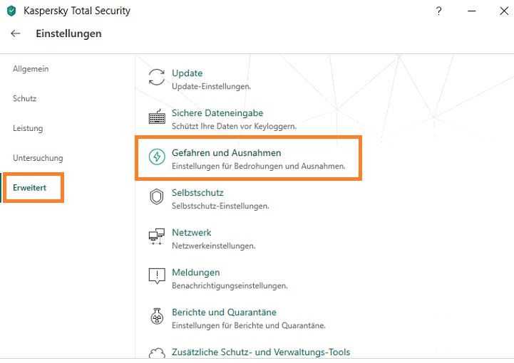
Öffnen Sie die Einstellungen Ihres Kaspersky und klicken Sie auf "Erweitert" → "Gefahren und Ausnahmen"
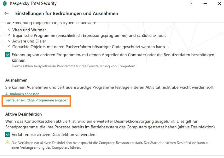
Gehen Sie nun in das Menü "Vertrauenswürdige Programme angeben" und wählen Sie dort Ihren Browser aus
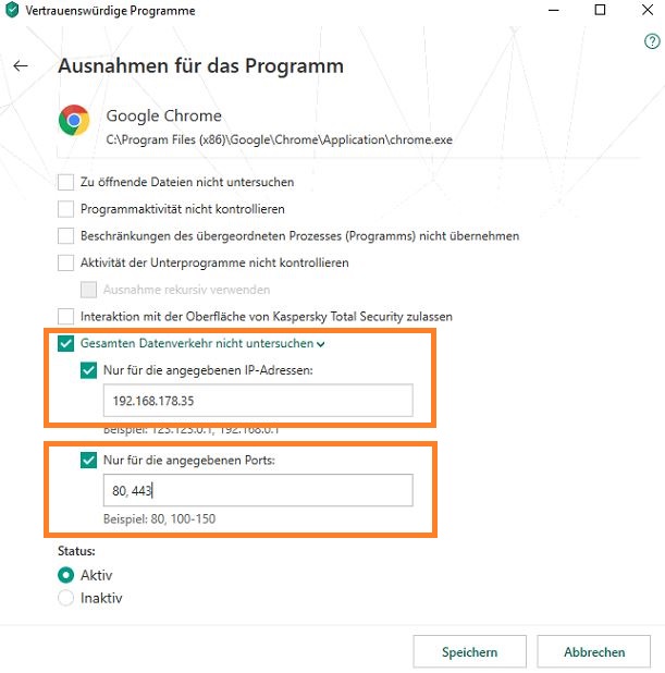
Da die Ausnahme ja nur für die IP Adresse der Alarmanlage gelten soll, aktivieren wir unter "Gesamten Datenverkehr nicht untersuchen" die Option "Nur für die angegebene IP-Adressen" und geben die IP Adresse der Alarmanlage ein.
Unter "Nur für die angegebenen Ports" schränken wir die Ausnahme noch weiter ein, so dass nur die für den Zugriff relevanten Ports dort zu finden sind (80, 443). Wenn Sie diesen Rechner für den Fernzugriff auf die Alarmanlage verwenden, geben Sie hier bitte auch noch den von Ihnen freigegebene externen Port an (z.B. 53080)
-
Userinterface extrem slow - Avast what to do?
-
Wenn die Alarmanlage extrem langsam reagiert, liegt dies in der Regel daran, dass ein Virenscanner die TLS 1.2 verschlüsselte Verbindung aufbricht. Da dies extrem rechenaufwendig ist, sorgt dies auch für extreme Verzögerungen im Seitenaufbau.
Wir empfehlen daher für die IP Adresse der Alarmanlage eine Ausnahme im Virenscanner hinzuzufügen.Um in Avast eine Ausnahme für eine IP Adresse hinzuzufügen, gehen Sie bitte folgendermaßen vor:
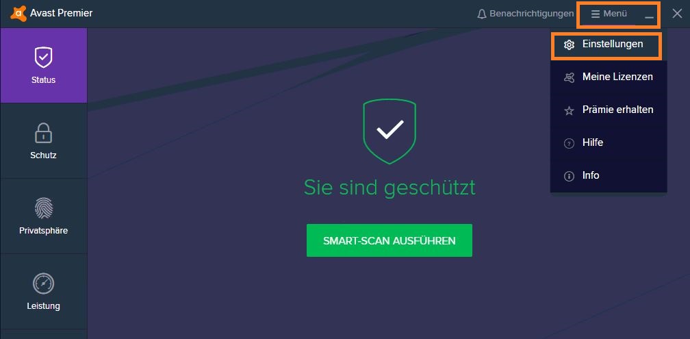
Öffnen Sie das Menü von Avast und klicken Sie auf "Einstellungen".
Gehen Sie dort in das Menü "Allgemein" → "Ausnahmen" und klicken Sie dann auf "Ausnahme Hinzufügen".
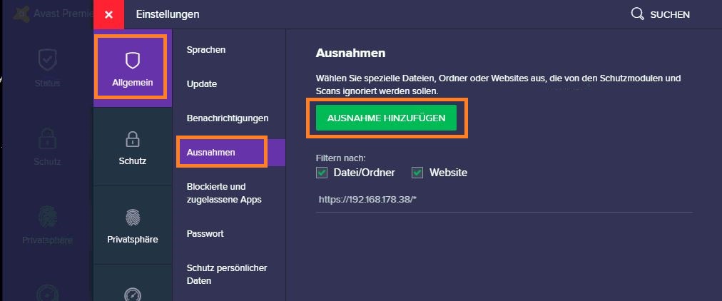
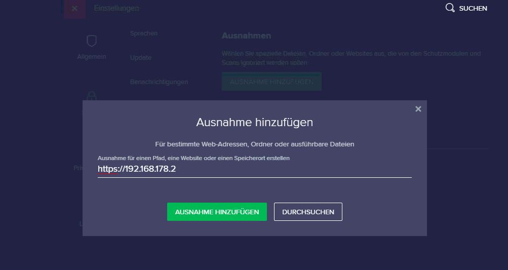
Geben Sie nun die IP Adresse Ihrer XT ein und klicken Sie danach auf "Ausnahme hinzufügen"
-
Camera integration of other manufacturers - type of authentication
-
When you add a camera of another manufacturer to your XT alarm panel, you need to mind the used authentication method:
A basic authentication commonly uses the structure "username:password@". In this case, please leave the option "Authentication via parameter" deactivated!
A digest authentication via parameter mostly uses a structure like "&user=username&password=password". In this case, please activate the option "Authentication via parameter".
-
Why are there display errors in the web interface since the last firmware update?
-
When updating the firmware of a device, we often add new functions or change the layout of the web interface. Since browsers often download the images of a website to load it faster in the future, this can lead to display errors after a firmware update.
The reason for these display errors is the cache of the browser in which older images are saved.To delete the cache of your browser and, thus, forcing the browser to load the new images, you can press strg+F5 (Windows) or cmd+alt+e (MAC).
If this does not work, please use the following manuals to delete the browser cache manually.Firefox
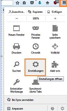
- Click on the three lines at the top right and open the settings of your Firefox.
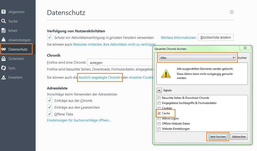
- Go to the menu "data privacy" → and check the following fields to delete only the cache of your Firefox and, then, reload the interface of the alarm panel:
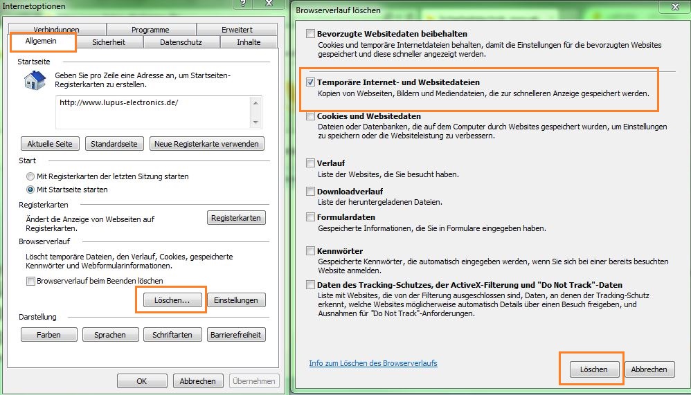
Internet Explorer
- Click on the cogwheel at the top right and open the internet options
- Please proceed as follows to delete the cache and temporary website information and, then, reload the interface of the alarm panel:
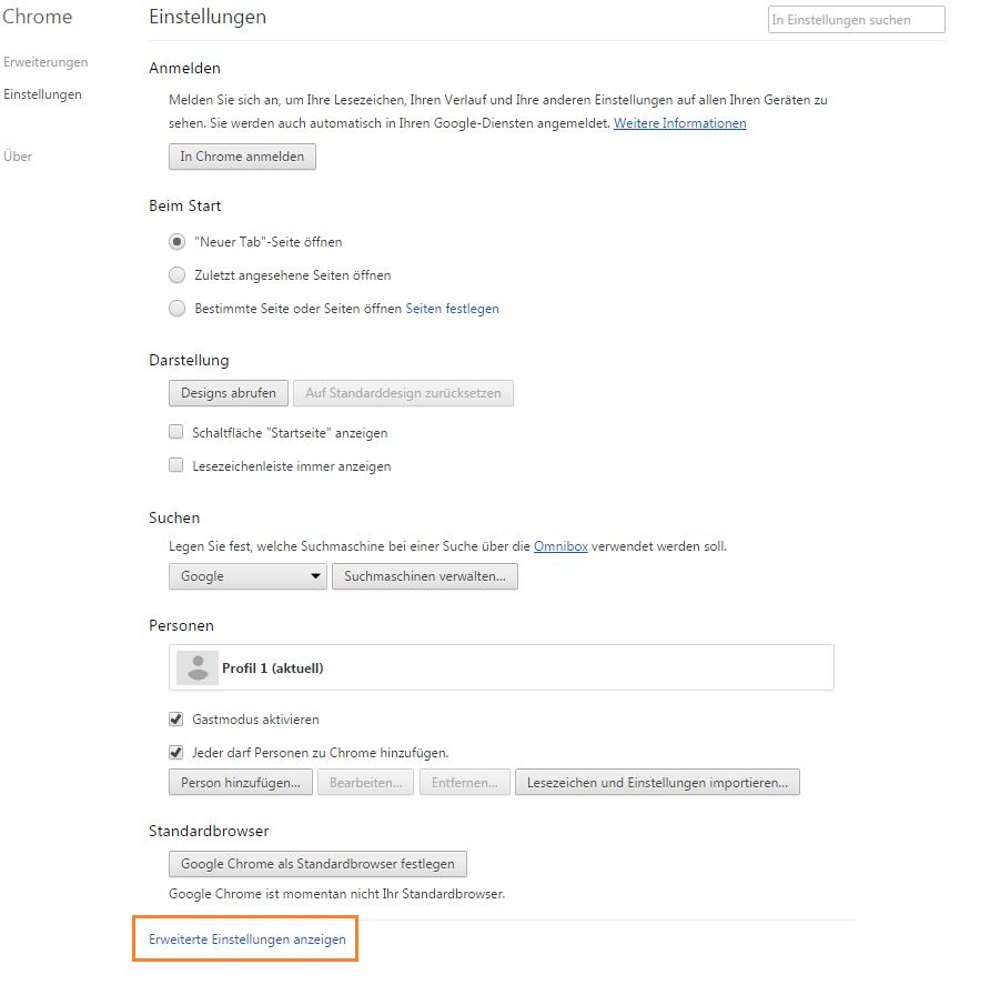
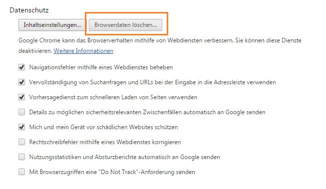
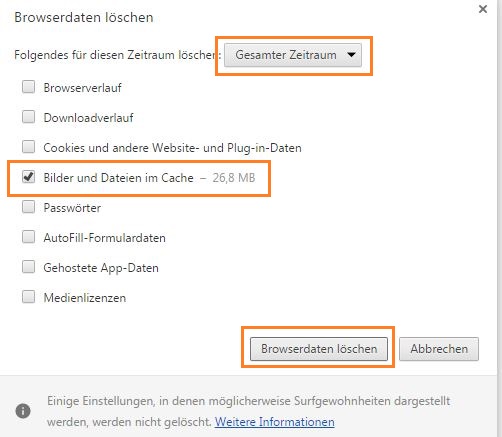
Google Chrome
- Click on the three points at the top right and go to "settings" → "advanced settings."
- Please proceed as follows to delete the cache and temporary website information and, then, reload the interface of the alarm panel:
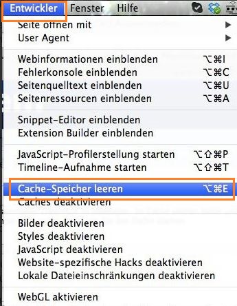
Safari using a MAC
- Click on the Menu "developer" → "delete cache" and, then, reload the interface of the alarm panel:
-
How can I control bus systems (e.g. KNX) with my XT alarm panel?
-
You can control other automation systems (e.g. KNX) by means of our relays. For instance, our 230V relay switches on or off according to the current mode of the alarm panel (arm / disarm) and is connected to a binary converter of your KNX bus system. Upon receiving the signal of our relay, the binary converter will act according to its programming and trigger other actions of your bus system.
-
What is the security risk in question involving ZigBee standards/protocols?
-
The risk described is small regarding a singular point in the initial, out-of-the-box joining (when the homeowner is installing a new device) or when a device is re-joining the network after losing contact with its parent – which is a few milliseconds of key exchange. The hack requires substantial knowledge and equipment and is unlikely to occur outside of the security community.
XT Alarm Panels XT1 Plus, XT2 (Plus), XT3, XT4
-
The XT main unit sounds every 30 seconds.
-
There are one or multiple failures listed under "System" → "Status" → "Panel" here you can choose "Ignore" to continue normal operation.
-
I still receive push notifications of an alarm panel after I have deleted the profile in my app.
-
In order to turn off the push notifications of your XT, you need to add the XT again to your LUPUS app. After you have reconnected the alarm panel to the app, go to the menu "Notifications" in your app and disable the push notifications for this smartphone. Afterwards, you can delete the profile of the alarm panel from your app.
Alternatively, someone else who is still connected to the XT can delete your smartphone from the list in the notifications menu.
-
How can I use the call list of my Fritz!Box with the XT alarm panel?
-
In order to use the call list of your Fritz!Box, you need to activate the port 1012. In order to do this, please proceed as follows:
Type in the combination #96*5* in a phone that is connected to your Fritz!Box and press call.
You will receive an activation signal.If you do not have a phone, you can also use the internal phone book of your Fritz!Box.
Just create a new contact with the above mentioned combination and use the phone book of your Fritz!Box to call this contact.Lastly, you need to enter the IP address of your Fritz!Box and the port 1012 in your XT in the menu "Settings" → "Panel" → "General Settings."
You can find further information for the activation of the call monitor here.
-
Is the autmatic door lock "Nuki" supported by the XT2 Plus panel?
-
Yes, you can use the Smarthome menu to control the Nuki door lock. For this, you need a "bridge" to your door lock.
Connect the Nuki bridge to your WIFI and connect your door lock to the bridge. Memorise the bridge IP, port, and token (can be found in the Nuki app in the bridge menu)
Enter these information in the XT menu "Settings" → "Device integration":
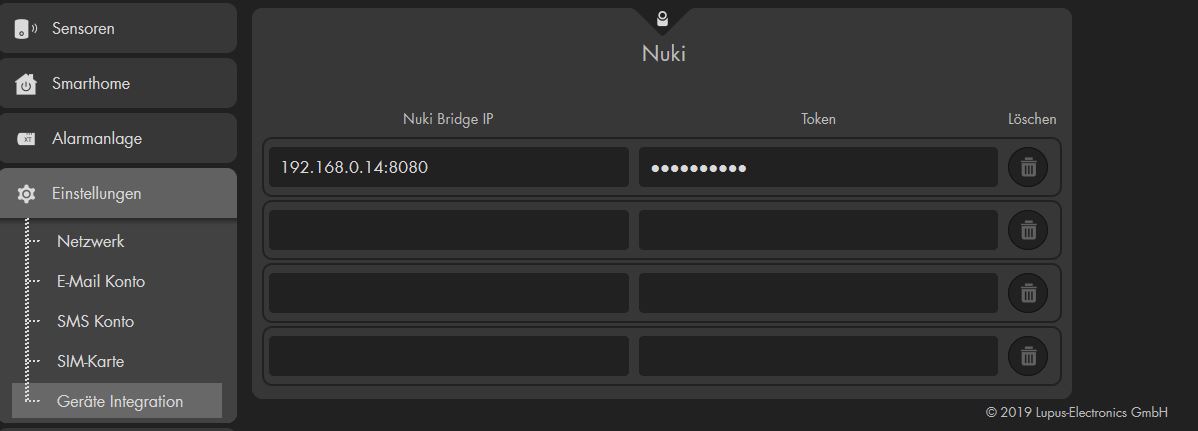
Mind the colon between the IP and the portNow, go to the menu "Sensors" → "Add" and klick in "start".
All door locks that are connected to your bridge are listed and can be added to the alarm panelYou can control the door lock via the menu "Smarthome" → "Wireless plugs" or create automation rules for the door lock in the menu "Smarthome" → "Automation".
Old version
NO LONGER REQUIRED WITH LATEST FIRMWARECommand to open:
http://IP-Adresse-Nuki:8080/lockAction?nukiId=123456789&action=1&token=123456Command to close:
http://IP-Adresse-Nuki:8080/lockAction?nukiId=123456789&action=2&token=123456The Nuki IP address, the ID, and the token are displayed in the bridge settings with the Nuki APP. API HTTP must be enabled.
XT Alarm Panels Sensors
-
PIR motion detector - trouble shooting
-
Please heed to the following information:
- It is important that the PIR motion detector can only function properly if it is installed in the correct height. Please install it between 1.8 and 2 meters (5.9 - 6.56 ft)
- If the place of installation is higher, you need to adjust its orientation
- If you press the test button for about five seconds, the motion detector will enter into a test mode for three minutes and the led will flash each time a motion is detected
- After each detected movement, the motion detector enters a rest period for three minutes during which no further motions will be detected.
-
PIR motion detector - What is the function of JP3?
-
If this jumper connects the two pins, the sensibility of the PIR motion detector is increased
-
Why does the alarm panel still display low battery after I have changed the batteries of a sensor?
-
When you change the batteries, we advice to discharge any residual voltage. Press the learn button of the sensor a few times before instering the new batteries.
-
One sensor displays CTRL Error. What does this mean?
-
This error occurs if the sensor does not respond while the alarm panel checks the status of the sensors.
It can be fixed by repeating the signal via e.g. Item No. 12050 LUPUSEC - LUPUSEC - Wireless Power device with meter and ZigBee Repeater.
The signal is repeated automatically by the mains socket.
XT Alarm Panels Smarthome
-
How do I correctly set up a home automation rule?
-
To set up a home automation rule, several steps are necessary:
- Open the menu "Sensors" → "List" → "Sensors" and press on "edit" (cogwheel) next to the sensor that shall trigger the home automation rule.
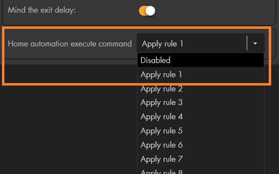
If you want to set up a rule that is not triggered by a sensor, please skip this step.
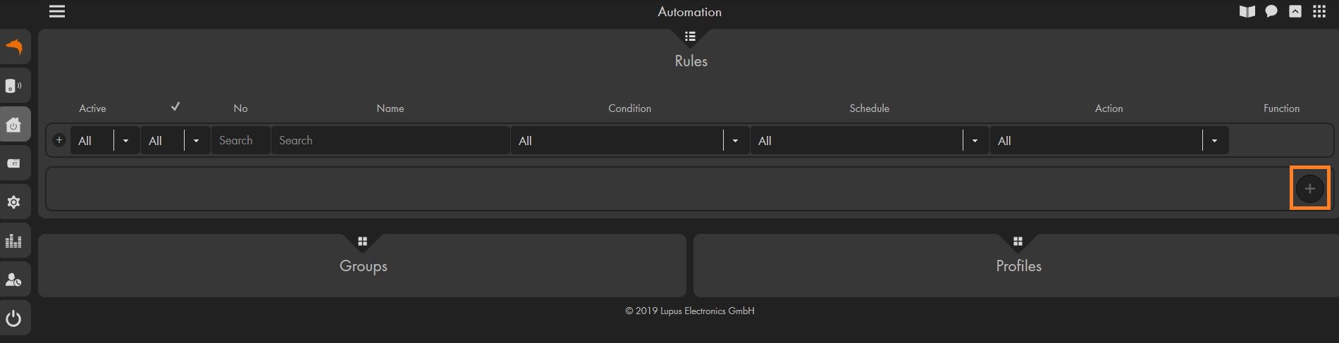
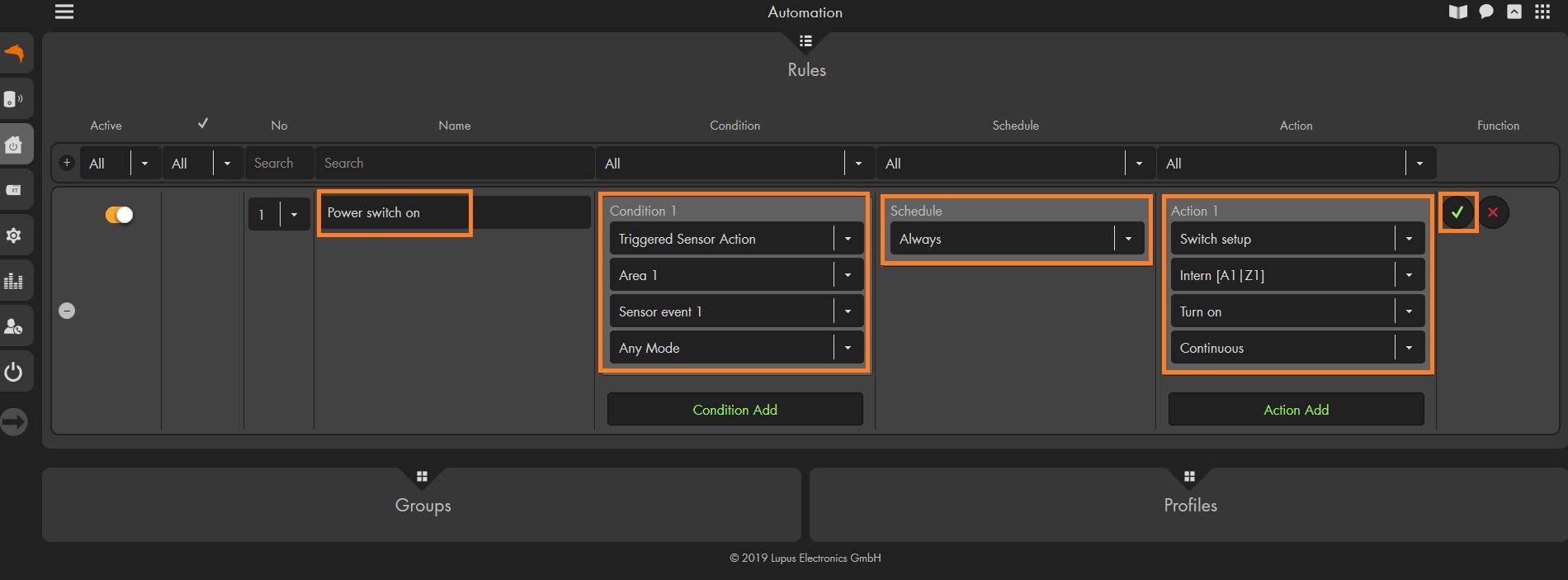
In the row "Home automation execute command," you can now define e.g. "Apply rule 1". - Open the menu "Smarthome" → "Automation" → "Rules" and create a new rule by pressing on the "+" symbol.
- You can now define a name for this automation. This will help you to identify the function of the automation later on.
In the column "Condition," you can set up a condition which will trigger the home automation. To use the "Rule 1" which we defined in the sensor above, please select "Triggered sensor action" and "Sensor event 1."
The "Schedule" allows you to define a time condition for this rule. If you select "always," this automation will always be performed when the condition is fulfilled.
The "Action" is the automation you want to perform if your condition and schedule settings are fulfilled.
In this example, every time our door contact triggers the sensor event 1, a wireless plug is switched on.
If you want that more than one condition needs to be fulfilled to trigger an automation, you can add additional conditions by pressing on the "+" symbol in the condition column. The same can be done to trigger multiple actions.
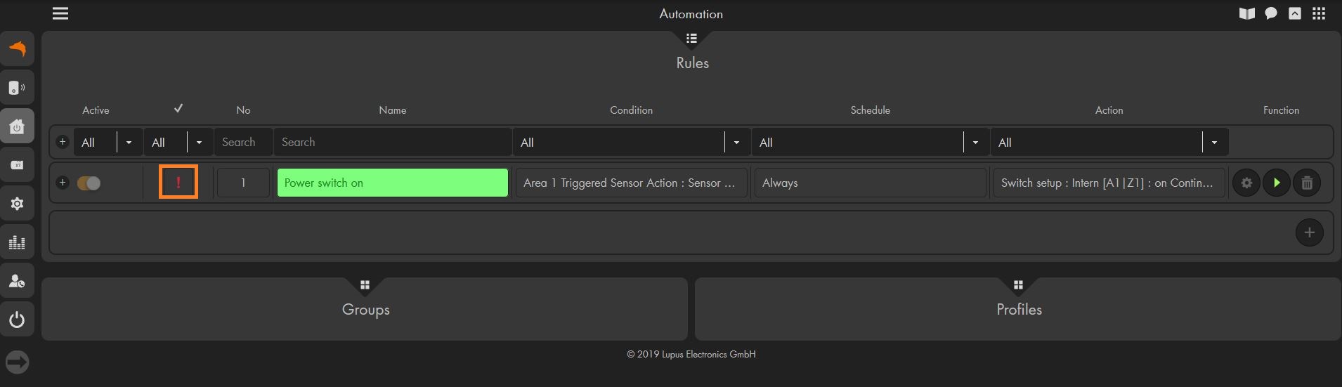
Click on the checkmark to create this rule. - Right now, this rule is not active – this is depicted by the red exclamation mark left to the number of the automation. This means that this rule is not part of the currently active profile.
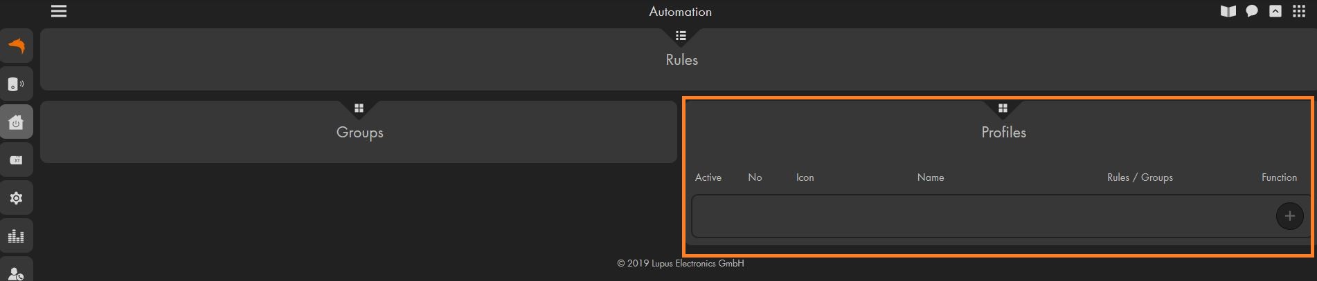
- To manage your profiles, use the pull down menu "Profiles"
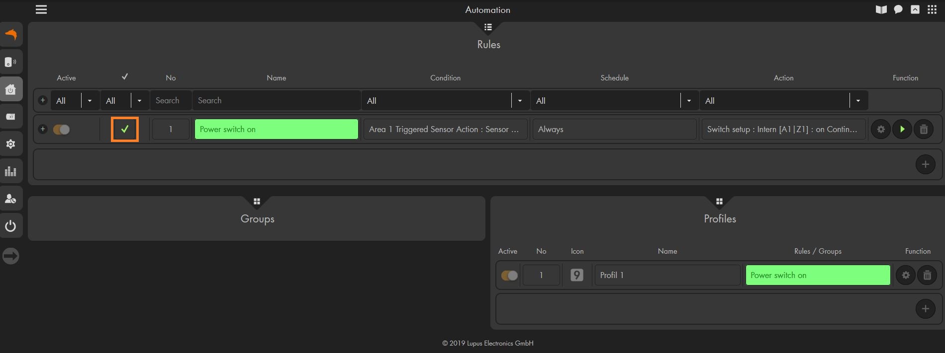
If have not already set up a profile, please click on the "+" symbol to create a new one. - Assign a name to your profile and add the rule we created above in the column "rules / groups."
Click on the checkmark when you are done. - In the image below, you see a finished rule that is assigned to an active profile. Additionally, a green checkmark is displayed next to the rule to show that this rule is currently active.

- Open the menu "Sensors" → "List" → "Sensors" and press on "edit" (cogwheel) next to the sensor that shall trigger the home automation rule.
-
Wireless power supply device - I cannot connect my wireless power supply device with my XT1 alarm panel.
-
The wireless wireless power supply device may not be the first device you connect to your XT.
Please start by connecting a different sensor.
-
Status display - Why doesn't my status display signal an alarm?
-
If your status display does not flash red when an alarm is triggered, please check the settings of the external sirens in the menu "Alarm system" → "Siren settings" → "Alarm settings". The status display will act according to these settings.
-
Warum haben meine ZigBee / Smarthome Geräte eine andere Reichweite als meine Gefahrenmelder?
-
Im Gegensatz zu unseren Gefahrenmeldern welche auf 868MHz senden, verwenden unsere Hausautomationsgeräte ein ZigBee Protokoll auf 2,4GHz. Dies stellt sicher, dass sich die Hausautomation und die Gefahrenmeldung nicht gegenseitig stören. Damit sind Sie und Ihr Heim immer bestens geschützt.
Aufgrund der Verwendung unterschiedlicher Frequenzen gibt es aber auch einen Unterschied in der Verbindungsreichweite der Smarthome Geräte und der Gefahrenmelder.
Allgemein hängt die Reichweite der Geräte, egal ob Gefahrenmelder oder Smarthome, immer stark von der Umgebung ab und wird durch Wände, Metall und andere Geräte im Funknetz unterschiedlich beeinflusst. Wie stark die Beeinflussung der Sendeleistung ist, kann man leider nicht pauschal sagen, da dabei natürlich jede Wohnung und jedes Haus individuell ist. Ein Gefahrenmelder mit der Frequenz 868MHz kann aber unter vergleichbaren Bedingungen eine höhere Reichweite haben als ein Smarthome Gerät auf 2,4GHz.In einem Haus gibt es daher, im Vergleich zu einer Fläche ohne Hindernisse, unterschiedliche Richtwerte für die Reichweite.
Alle Smarthome Geräte werden in einem Haus etwa eine Entfernung von 15-20 Metern abdecken können. Diese Entfernung ist aber keinesfalls die Maximalreichweite, sondern kann mittels unseres ZigBee Repeaters um ein vielfaches erhöht werden. Sollte die Verbindung schon bei einer geringeren Entfernung aus irgendeinem Grund zu schwach sein, hilft dieser Repeater natürlich auch.
Die Funksteckdose mit ZigBee Repeater ist nicht nur ein praktisches Gerät zur für Ihr Smarthome, sondern verstärkt auch automatisch die Signale anderer ZigBee Geräte in Ihrem ZigBee Netzwerk. Eine einzelne Steckdose kann bis zu 10 Signale anderer ZigBee Geräte verstärken. Der Clou, die Steckdosen können hier auch in Reihe verwendet werden, so dass die Reichweite Ihres ZigBee Netzwerks um ein vielfaches erhöht wird.
Wie stellen Sie sicher, dass die ZigBee Repeater richtig arbeiten?
Dafür ist es lediglich notwendig, dass die ZigBee Repeater-Steckdose sowie die Smarthome Geräte welche verstärkt werden sollen, in der Zentrale angelernt sind. Die Repeater-Steckdose muss dann noch an der gewünschten Position in eine Steckdose gesteckt werden. Ob die Repeater-Steckdose eingeschaltet oder ausgeschaltet ist, ist dabei nicht wichtig. Der Rest geschieht vollständig automatisch.
-
How do I setup a simulation of presence?
-
Automation: "Zufällige Auführung" Allgemein
Um eine Anwesenheitssimulation zu erstellen bietet die XT Zentrale die Möglichkeit einer zufälligen Ausführung eines Automationsbefehls. Dabei haben Sie die Wahl, ob die Automation garantiert in dem ausgewählten Zeitraum ausgeführt werden soll, oder ob diese nicht garantiert Ausgeführt werden soll.
Allgemein gilt für die Ausführung:
- Sie definieren in der Automation einen Zeitrahmen währenddessen die zufällige Ausführung stattfinden kann.
- In diesem Zeitrahmen wird die Wahrscheinlichkeit dann auf die einzelnen Minuten aufgeteilt. Das heißt, je länger der Zeitrahmen, desto geringer ist die Wahrscheinlichkeit der Ausführung pro Minute.
Bei einem Zeitintervall von 10 Minuten, hätte jede Minute eine Wahrscheinlichkeit von 10% die Automation zufällig auszulösen. - Bei einer garantierten Ausführung ist in der letzten Minute des Zeitraums die Ausführung garantiert (sollte die Ausführung nicht schon stattgefunden haben).
- Definieren Sie bitte immer einen Zeitraum! Ein undefinierter Zeitraum (z.B. "Immer") würde dazu führen, dass die Wahrscheinlichkeit der Ausführung für einen unbestimmten Zeitraum definiert wird und daher die Wahrscheinlichkeit der Ausführung pro Minute eshr gering ist.
Beispiel für eine Anwesenheitssimulation
Bedingung Zeitraum Aktion Zufällige Ausführung Jeden Tag 22:00 bis 22:10 Zone einschalten Innerhalb jeder der Minuten dieses Zeitraums besteht dann, innerhalb der jeweiligen Minute, eine Chance von 10%, dass die Aktion ausgeführt wird.
Anwendungsbeispiel
Für eine komplette Anwesenheitssimulation über an einen oder mehreren Abenden könnten Sie eine Automation dieser Art anlegen:
Bedingung Zeitraum Aktion Zufällige Ausführung Jeden Tag 18:34 bis 23:23 Zone einschalten für - Diese Automationen sorgen dafür, dass zwischen 18:34 und 23:23 unter Umständen ein Relais / eine Funksteckdose für eine von Ihnen definierte Zeit eingeschaltet wird.
- Nachdem der von Ihnen definierten Zeit wird das Relais / die Funksteckdose automatisch wieder ausgeschaltet und könnte erneut in diesem Zeitintervall durch die Automation eingeschaltet werden.
- Wenn Sie bei der "zufälligen Ausführung" noch das die Einstellung "garantierte Ausführung: an" wählen, wird die Regel spätestens in der letzten Minute des jeweiligen Intervalls ausgeführt. Dies erlaubt Ihnen sicherzustellen, dass ein Licht tatsächlich einmal an geht – bedeutet aber auch, dass eine solche Regel leichter als Simulation erkannt werden könnte.
- Sie können die Bedingung auch mit "Modus - Arm" kombinieren, so dass die zufälligen Ausführungen nur stattfinden wenn die Zentrale im Arm Modus ist.
Natürlich können Sie hier auch andere Abhängigkeiten definieren: z.B. nur unterhalb bestimmter Lux Werte.
Bitte beachten Sie, dass dies nur Beispielwerte sind, welche natürlich nicht in dieser Form 1:1 übertragen werden sollten.
-
Is it a phase angle or section dimmer?
-
This is a phase angle dimmer.
-
How to calculate the inrush current of the shutter motor?
-
Please be aware of the inrush current of the motor of your shutter when using our shutter relay. The inrush current is mostly not found in the technical data of your motor, but can be calculated in the following way.
Nominal current = Power / 230V
Maximum current = Nominal current x 1,414
Inrush current = Maximum current x 2A shutter motor with a power of 120W, the calculation would look the following:
Nominal current: 120 W / 230V = 0,52A
Maximum current: 0,52A * 1,414 = 0,74A
Inrush current: 2x 0,74A = 1,48AA shutter motor with a power of 120W / 0.52A has an inrush current of 1.48A for the first 20-30ms.
Please make sure, that the inrush current of your motor is lower than the maximal load of our shutter relay. Otherwise, the shutter relay can be damaged. If the inrush current of your shutter is higher, please use a suitable cut-off relay between the shutter relay and the motor.
XT Alarm Panels Control Units
-
Keypad - I cannot arm my alarm panel with the code 0000.
-
This code is used to connect the keypad to the alarm panel (installer mode). The PIN Codes to control the alarm panel can be set in the webinterface in the menu Home -> PIN Codes.
-
Is the outdoor keypad compatible with the XT1?
-
The outdoor keypad is compatible with the XT1. However, the four home automation buttons (F1 – F4) and the Status request cannot be used with the XT1.
-
Why doesn't my outdoor keypad react to any commands?
-
The outdoor keypad features a stand-by function in order to save power. During the stand-by mode, the outdoor keypad will not accept any commands.
You can end the stand-by mode by touching the outdoor keypad e.g. with the palm of your hand.
In the figure below, the area which you need to touch with more than one finger (preferably the palm of your hand) to end the stand-by mode is marked. After you have quit the stand-by mode, you can enter your PIN code and control your alarm panel via the outdoor keypad: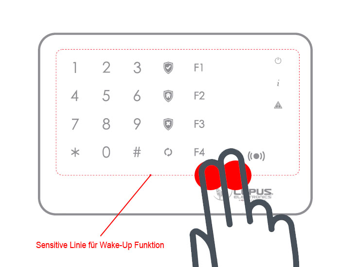
-
Why can't I add my new V2 control units to my alarm panel?
-
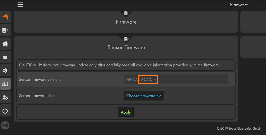
In order to be able to install the new V2 control units, you need to install the latest firmware (at least version 0.0.2.17) and the sensor firmware 35E that is included in the firmware file.
XT Alarm Panels Sirène
-
The outdoor siren (V1) does not stop
-
Please switch SW1 off again after you have added the siren to the alarm panel.
-
Outdoor and indoor siren do not sound an alarm
-
Please check if the alarm for the external sirens is enables in the menu "Alarm system" → "Siren settings" → "Alarm settings".
-
Outdoor siren V2 - Which settings can be changed with the XT1?
-
There are three available settings:
- You can deactivate the tampering protection for one hour (e.g. to install the siren or change the batteries).
- You can activate or deavtivate the confirmation tones for arming or disarming.
- You can activate or deavtivate the confirmation tones during the entry and exit delay. Depending on the version of your siren, this will also activate or deactivate the flash during the entry and exit delay.
- For more information regarding the version of your siren, pleaes refer to the FAQ "Outdoorsiren V2 and XT1 - How can I set up my outdoor siren V2?"
-
Outdoor siren V2 - Which settings can be changed with the XT1 Plus, XT2 (Plus), XT3, and XT4?
-
There are three available settings:
- You can deactivate the tampering protection for one hour (e.g. to install the siren or change the batteries).
- You can activate or deactivate the confirmation tones for arming or disarming.
- You can activate or deactivate the confirmation tones and signals during the entry and exit delay.
Additionally, the XT2 (Plus) offers you the following advanced settings.
- You can set the alarm volume.
- You can define if the outdoor siren shall signal a doorbell signal.
- You can set if the outdoor siren shall sound an alarm in home mode.
- You can set if the outdoor siren shall sound an alarm in arm mode.
- You can activate or deactivate the siren strobe.
- You can activate or deactivate the confirmation strobe
- You can activate or deactivate the exit strobe.
- You can activate or deactivate the entry strobe.
- You can activate or deactivate the trigger strobe.
- You can set the volume of the exit delay.
- You can set the volume of the entry delay.
For more information concerning the available settings, please refer to the latest online manual of the XT2 (Plus).
-
How can I deactivate the signals of the siren?
-
Open the menu "Alarm system" → "Siren settings" → "Sirens".
Click on:
- "Confirmation signal off"
- Click on "Apply now"
- You will hear a confirmation tone of the siren that signifies, that the change was saved
Click on
- "Input off"
- Click on "Apply now"
- You will hear a confirmation tone of the siren that signifies, that the change was saved
The siren will always sound warning signals (e.g. five signaltones upon arm or disarm signifies an open tampering contact of the siren) independently of these settings.
-
Does the mini indoor siren Plus support the doorbell function?
-
Yes, the current mini indoor sirens (on the market since 2018) support the doorbell function!!
-
Why does my outdoor siren V2 sounds five times when I arm or disarm the alarm panel?
-
This is an error notification which cannot be deactivated.
It signals you that the tampering contact of your outdoor siren is open.
This error notification can already sound before the alarm panel displays an open tampering contact, thus, giving you time to react before a complete tampering alarm is triggered.
-
Outdoorsiren V2 and XT1 - How can I set up my outdoor siren V2?
-
XT1 siren settings
The following table displays how you can set up your outdoor siren V2 with the XT1 alarm panel. Please note the different versions of the outdoor siren.
Please use the menu "Sensors" → "Devices" for these settings.
Settings For sirens since M0216 (8L05 on the chip) For sirens before M0216 (8L04 on the chip) Sirens since 8L07 Confirmation tone on / Entry on Last sound upon arming on
Last LED flash on
Sound and flash during the delay time onLast sound upon arming on
Last LED flash on
Sound and flash during the delay time onLast sound upon arming on
Last LED flash on
Sound and flash during the delay time onConfirmation tone off / Entry on Last sound upon arming off
Last LED flash off
Sound and flash during the delay time onLast sound upon arming off
Last LED flash on
Sound and flash during the delay time onLast sound upon arming off
Last sound upon arming on
Sound and flash during the delay time onConfirmation tone off / Entry off Last sound upon arming off
Last LED flash off
Sound and flash during the delay time offLast sound upon arming off
Last LED flash on
Sound and flash during the delay time offLast sound upon arming off
Last LED flash on
Sound during the delay time off and flash during the delay time onConfirmation tone on / Entry off Last sound upon arming on
Last LED flash on
Sound and flash during the delay time offLast sound upon arming on
Last LED flash on
Sound and flash during the delay time offLast sound upon arming on
Last LED flash on
Sound during the delay time off and flash during the delay time on
XT Alarm Panels XT1 - EOL
-
The network LED of my XT1 flashes.
-
This signals that the network connection is initialised. It will stop flashing after you have set up the Contact-ID (e.g. copy 'rptn://ACCT@server:port' into the field URL 1 )
-
Problems SMS service / error code -608
-
Due to changes performed by any-sms and CM-Telecom, it is no longer possible to use these providers to send short messages with an XT1 alarm panel.
Please contact our support team via e-mail or telephone.
This problem only occurs with the XT1 - newer alarm panels can still use any-sms.
-
I cannot access the alarm panel with Google Chrome on my Android device.
-
Please choose to access the desktop version of the alarm panel or use an alternative browser (e.g. Firefox or Opera).
-
I cannot access my XT1 via webbrowser and App
-
This can be triggered by a security function. Please follow these instructions:
- 1. Restart the alarm panel by switching the battery off and unplugging the mains adapter for 2-3 seconds.
- 2. Deactivate UPNP in the network settings of the XT and manually set up a port forwarding in your router.
- 3. Do not use the port 80 as your public port! Select a different, 5-digit port as your public port (e.g. 53080).
Cameras General
-
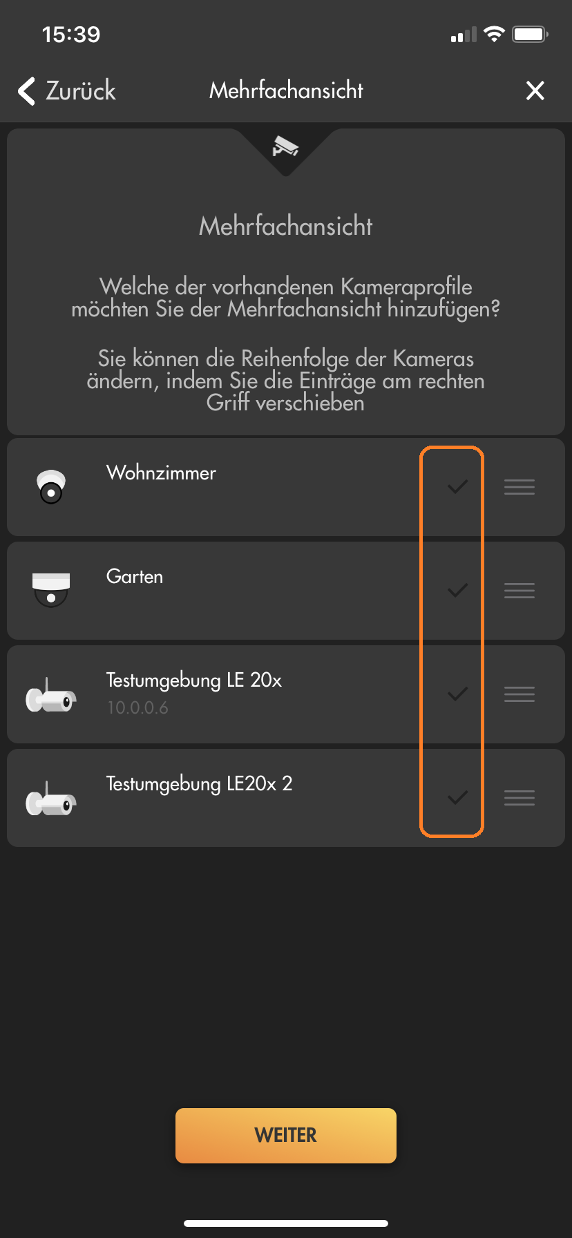
How can I setup a Multiview in my app?
-
Yes, you can set-up a Multiview in our iOS and Android App. In order to to so, please follow these instructions:
- Add all of your cameras as individual profiles to the app.
- Create a new profile in the app.
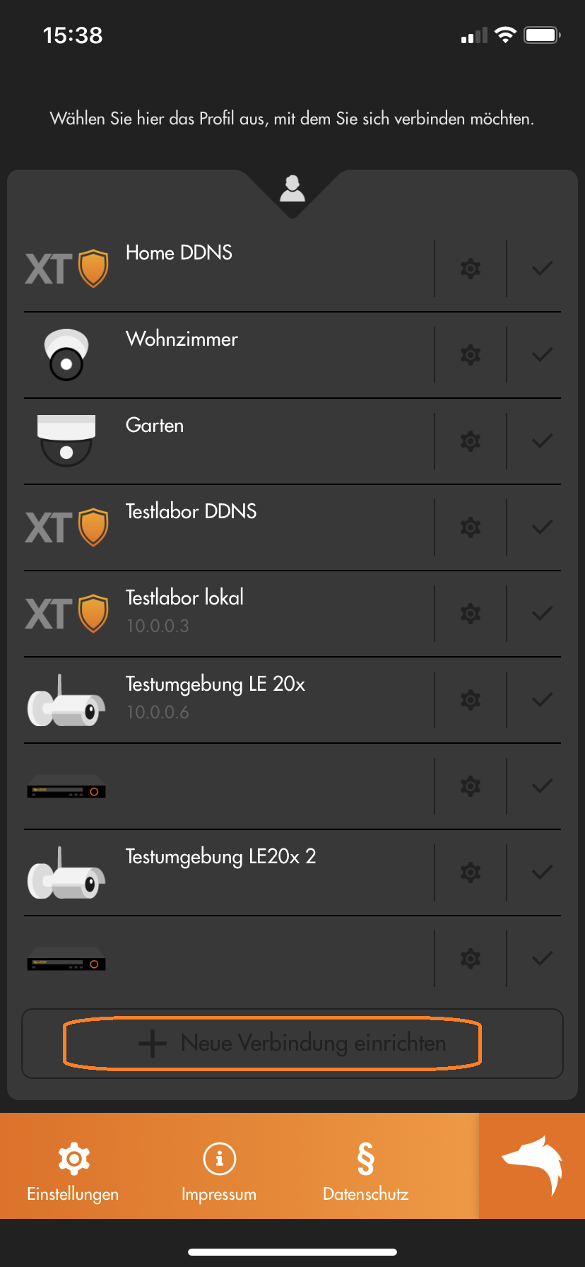
- Choose "Expert" or "Assistant".
- If you chose "Expert":
- Select "Multiview" as the "Device type".
- Inset a "Name" for this Multiview and select the cameras you want to add to the Multiview.
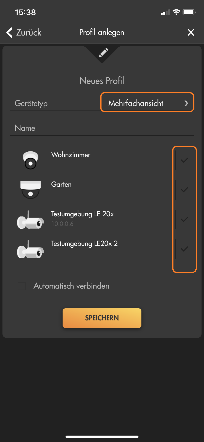
- Klick on "Save".
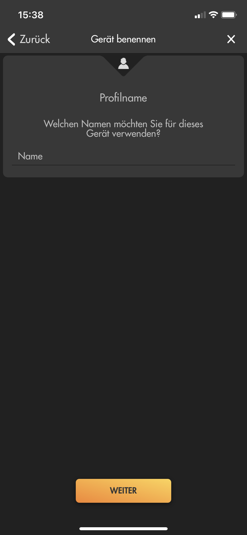
- If you chose "Assistant":
- Insert a name for the Multiview profile.
- Select "Multiview" as "Device type".
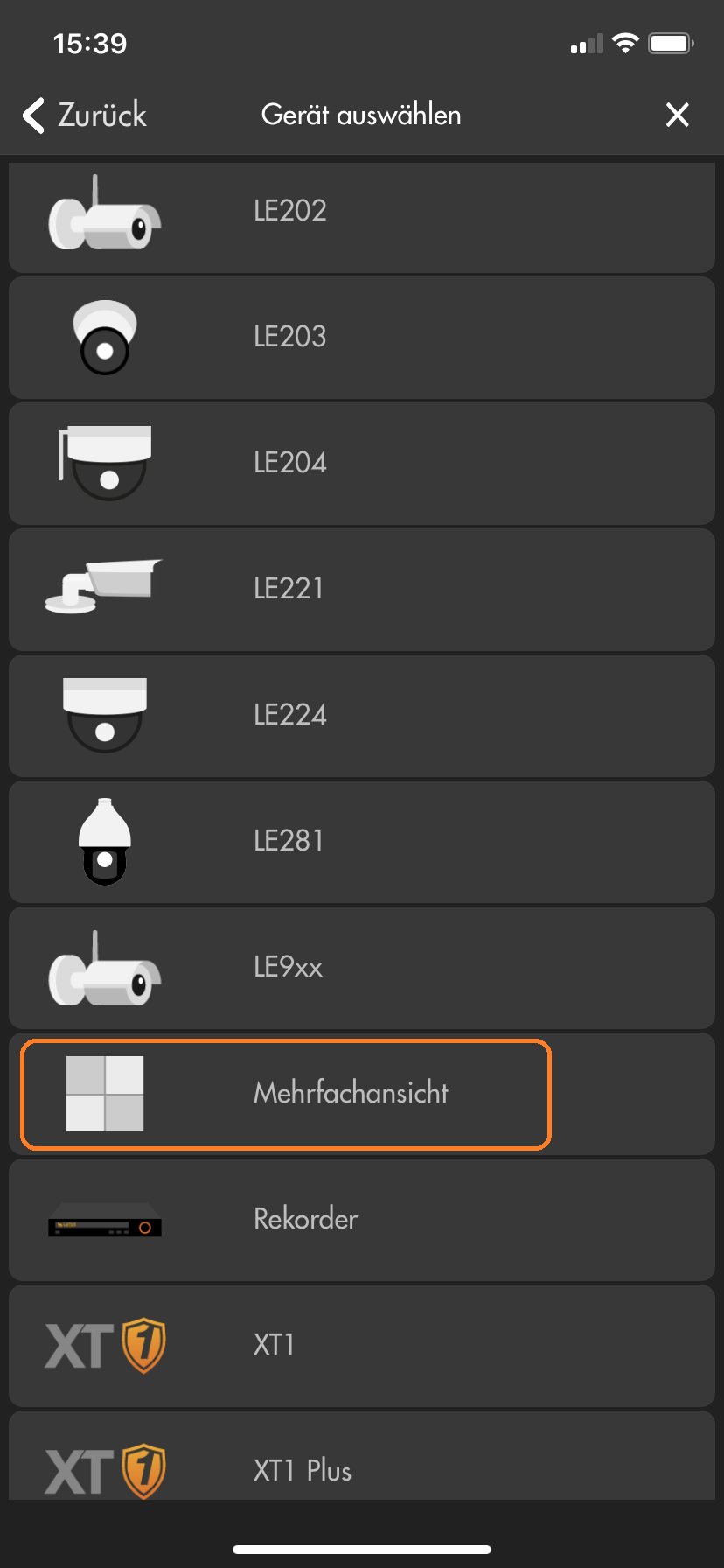
- Select the cameras you want to add to the Multiview.
-
Which camera supports which detection method (e.g. motion detection)?
-
Einfach Bewegungserkennung:
Die Kamera erkennt Bewegungen aufgrund von Änderungen der Pixel im Bild. Dafür stehen mehrere Filter zur Auswahl (4 Bereiche mit individueller Empfindlichkeit und Grenzwerten). Bei der einfachen Bewegungserkennung können auch Wettereffekte und leblose Objekte (z.B. Bäume / Äste) zu einer Auslösung der Bewegungserkennung führen. Hier finden Sie eine Textanleitung und eine Videoanleitung zur einfachen Bewegungserkennung unserer Kameras.Intelligente Bewegungserkennung V1:
Bei der intelligenten Bewegungserkennung V1 prüft eine KI in der Kamera, ob sich im einstellbaren Erkennungsbereich ein Mensch oder Fahrzeug bewegt. Die Erkennungsdistanz dieser KI liegt bei etwa maximal 6-12m (Reichweite und Zuverlässigkeit ist auch abhängig von Blickwinkel und Lichteinfall). Für eine Erkennung muss ein Mensch mindestens 160x160 Pixel im Bild ausfüllen und darf nicht größer aus zwei Drittel des Bilds sein (sowohl in Breite wie auch Höhe).Virtueller Grenzzaun:
Ein virtueller Grenzzaun erlaubt Ihnen Aufnahmen auszulösen, wenn ein Objekt mit einstellbarer Minimal- und Maximalgröße eine Linie überschreitet. Auch die Richtung der Linienüberschreitung ist einstallbar. Bestimmte Kameramodelle können auf diese Linienüberschreitung zusätzlich eine intelligente Bewegungserkennung anwenden und per KI weiter Filtern, ob es sich dabei um einen Menschen oder ein Fahrzeug gehandelt hat.Intelligente Bewegungserkennung V2 (neueste Version 2021):
Bei der intelligenten Bewegungserkennung V2 prüft eine KI in der Kamera, ob im einstellbaren Erkennungsbereich ein Mensch oder Fahrzeug bewegt. Die Erkennungsdistanz dieser KI liegt bei etwa maximal 26 (Mensch) /38m (Fahrzeug). Die optimale Erkennung eines Menschen findet ab etwa 6m statt. Die neue Version 2 der intelligenten Bewegungserkennungs-KI ist eine sehr große Verbesserung der KI der Vorgängerversionen mit annähernd 100% Genauigkeit bei der Erkennung von Menschen und Fahrzeugen. Für eine Erkennung muss ein Mensch mindestens 70x70 Pixel im Bild ausfüllen und darf nicht größer aus zwei Drittel des Bilds sein (sowohl in Breite wie auch Höhe). Hier finden Sie eine Anleitung zur Einstellung der intelligenten Bewegungserkennung unserer LE 232.Netzwerkkamera Einfache Bewegungserkennung Intelligente Bewegungserkennung V1 Virtueller Grenzzaun Intelligente Bewegungserkennung V2 (neueste Version 2021) LE 202 Ja Nein Nein Nein LE 203 Ja Nein Nein Nein LE 204 Ja Nein Nein Nein LE 221 Ja Ja Ja (inkl. Intelligente Bewegungserkennung V1) Nein LE 224 Ja Ja Ja (inkl. Intelligente Bewegungserkennung V1) Nein LE 228 Ja Ja Ja (inkl. Intelligente Bewegungserkennung V1) Nein LE 232 Ja Ja Ja (inkl. Intelligente Bewegungserkennung V2) Ja LE 281 Ja Ja Ja (inkl. Intelligente Bewegungserkennung V1) Nein Rekorder LE 918 4K / 926 4K Abhängig von der verwendeten Netzwerkkamera Abhängig von der verwendeten Netzwerkkamera Abhängig von der verwendeten Netzwerkkamera Abhängig von der verwendeten Netzwerkkamera LE 820/821 Ja Ja Ja (inkl. Intelligente Bewegungserkennung V1) Nein
-
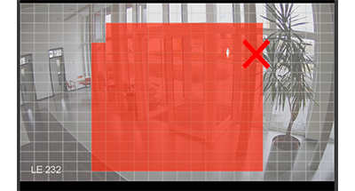
Why can’t I see anything in night-vision? Why is the video overexposed?
-
Die Ausrichtung einer Kamera hat einen erheblichen Einfluss auf das Bild in der Nachtsicht.
Befindet sich ein Objekt vor der Kamera, reflektiert dieses das IR-Licht und wird dadurch in der Nachtsicht für die Kamera sichtbar. Ist das Objekt zu nah vor der Kamera, kann es zu einer Überbelichtung kommen. Eine solche Überbelichtung durch Hindernisse wird von der Kamera erkannt und die Kamera regelt automatisch die Stärke der IR-LEDs herunter. Dies sorgt dafür, dass man zwar das Hindernis sieht und dieses nicht überbelichtet ist, aber oft ein Großteil des restlichen Bildes unterbelichtet / zu dunkel ist.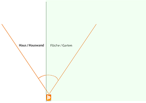
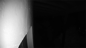
In diesen Bildern sehen Sie, dass die Kamera im 90°-Winkel entlang einer Wand ausgerichtet ist. Dadurch ist die Wand zu etwa 50 % im Fokus der Kamera und reflektiert auf kürzeste Distanz bereits das IR-Licht. Um eine Überbelichtung zu verhindern, regelt die Kamera die Stärke der IR-LEDs automatisch herunter. Dadurch ist die Wand sehr gut zu erkennen, aber im rechten Bereich des Bilds nichts mehr von der Fläche vor der Wand.
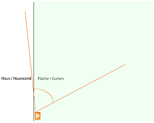
In diesen Bildern sehen Sie, dass die Wand nicht mehr für eine Überbelichtung sorgt – Sie sehen im Vergleich zum ersten Bild den Weg und den Garten.
Das Gebüsch und das Vordach sorgen als zu nahe Hindernisse (in diesem Fall unter 2 Meter Abstand) weiterhin dafür, dass die Kamera die IR-LEDs herunterregelt und der Hintergrund daher nicht komplett ausgeleuchtet wird / dunkler erscheint.Stellen Sie immer sicher, dass sich keine Hindernisse in kurzer Distanz vor der Kamera befinden. Jedes Hindernis – egal ob Hauswand, Gebüsch, Baum oder ähnliches – reflektiert das IR-Licht und kann dazu führen, dass die Kamera die Stärke der IR-LEDs verringert, um eine Überbelichtung zu verhindern.
Achten Sie bei der Überwachung Ihres Gebäudes darauf, dass die Hauswand nur einen geringen Teil des Bildes einnimmt.
In folgendem Video sehen Sie, wie sich die IR-Ausleuchtung in Abhängigkeit der Ausrichtung der Kamera ändert:
-
How do I set up the WIFI for my camera?
-
Wie stelle ich die WLAN Verbindung meiner Kamera her?
Um eine Kamera mit Ihrem WLAN zu verbinden, ist es notwendig, die Daten Ihres WLANs auf der Kamera zu hinterlegen. Dazu müssen Sie zuerst kabelgebunden auf die Weboberfläche der Kamera zugreifen (sollten Sie nicht wissen wie Sie zu dieser gelangen, erfahren Sie hier mehr.
Die WLAN Einstellungen können Sie hinterlegen indem Sie Ihr WLAN aus der Liste im Schnellinstaltionsmenü auswählen und dann Ihr WLAN Passwort eingeben.
Alternativ müssen Sie in die Einstellungen der Kamera (entweder über den Punkt "Einstellung" oder das Zahnrad Symbol am oberen Rand) gehen.
Unter Netzwerk finden Sie den Menüpunkt "Wireless Einstellungen" (LE 9xx) / "WIFI" (LE 201) / "WLAN" (LE 200).Bitte beachten Sie, dass eine Kamera, nachdem Sie sie mit Ihrem WLAN verbunden haben von Ihrem Router eine neue IP Adresse zugeteilt bekommt (falls Sie DHCP verwenden). Die LE 201 hat immer zwei unterschiedliche IP Adressen - eine Kabelgebundene und eine für WLAN - diese wird Ihnen bei der LE 201 unter Netzwerk oder im WIFI Menü angezeigt.
LE 9xx ("Einstellungen" → "Netzwerk" → "Wireless Einstellungen"):
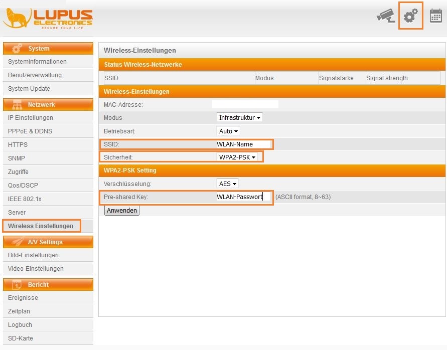
- SSID: hier müssen Sie den Namen Ihres WLAN Netzwerks exakt eintragen.
- Sicherheit: Wählen Sie hier die Verschlüsselung Ihres WLANs.
- Verschlüsselung: Wählen Sie TKIP oder AES je nach Einstellung in Ihrem Router.
- Pre-shared Key: Geben Sie hier Ihr WLAN Passwort ein.
- Klicken Sie auf "Anwenden" um die Einstellungen zu übernehmen.
LE 200 ("Einstellungen" → "Netzwerk" → "WLAN"):
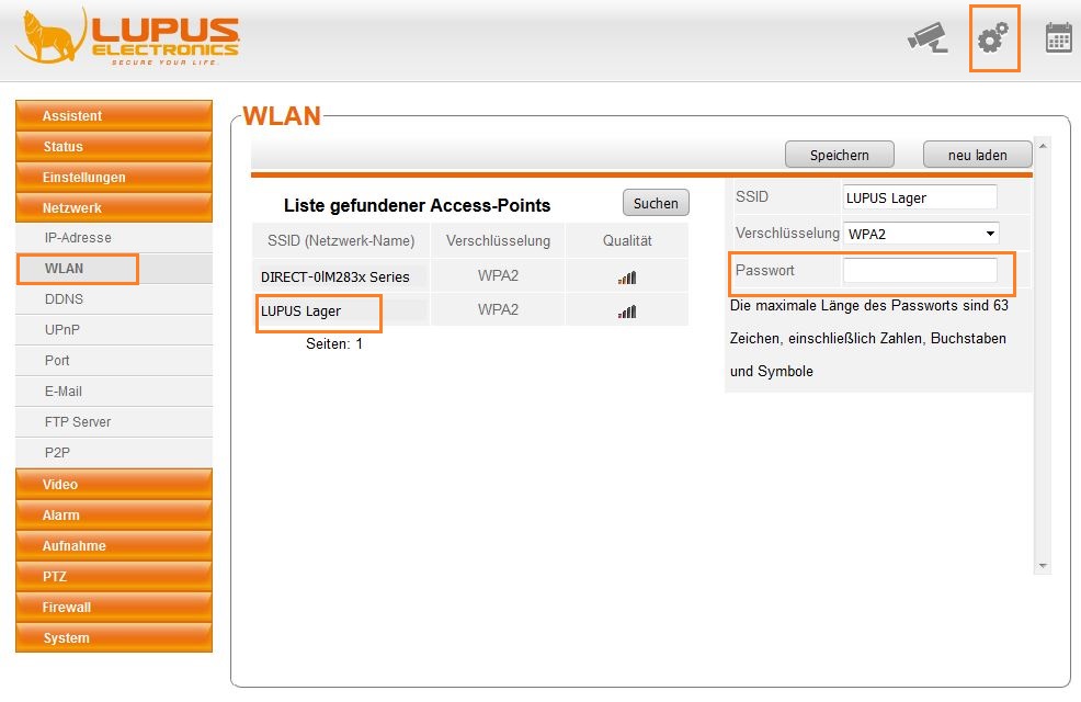
- Wählen Sie mittels Doppelklick das WLAN Netzwerk aus mit welchem Sie die Kamera verbinden möchten.
- Verschlüsselung: Geben Sie hier Ihr WLAN Passwort ein.
- Klicken Sie auf "Speichern" um die Einstellungen zu übernehmen.
LE 201 ("Einstellungen" → "Netzwerk" → "WIFI"):
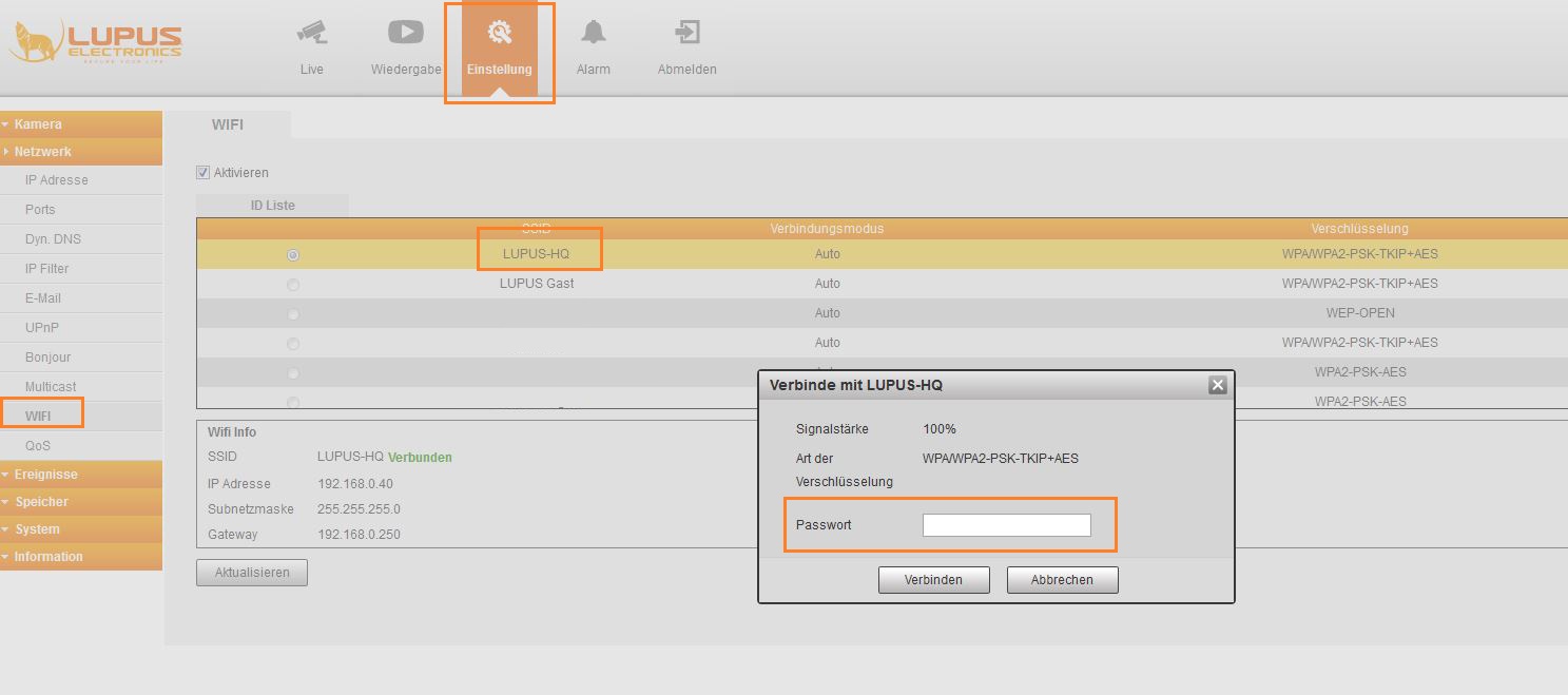
- Klicken Sie auf den Namen des WLANs mit dem Sie die Kamera verbinden möchten.
- Passwort: Geben Sie Ihr WLAN Passwort ein.
- Klicken Sie auf "Verbinden" um die Kamera mit Ihrem WLAN zu verbinden.
-
How much storage space do I need?
-
Please note that these are estimated record times for a continuous recording. However, the record time of a continuous recording is influenced by the amount of movement in the image - the more movement there is, the more storage space is required.
Thus, these times can only serve as an indication of the storage space you might require.
The record time is estimated for one camera with 25 frames per second.
Resolution Storage space Estimated record time 720p 32Gb 21 Stunden 1Tb 28 Tage 1080p 32Gb 9 Stunden 1Tb 12 Tage 4K 32Gb 2 Stunden 1Tb 3 Tage
-
What happens when the SD card of the camera is full?
-
When the SD card of the camera is full, the oldest records will be deleted automatically and replaced with new ones. You do not need to delete the recordings manually.
-
I cannot play the avi files I receive via e-mail.
-
Some e-mail providers (e.g. strato) shorten the header of the send avi files. This is the reason for this problem.
Please use a different e-mail provider.
-
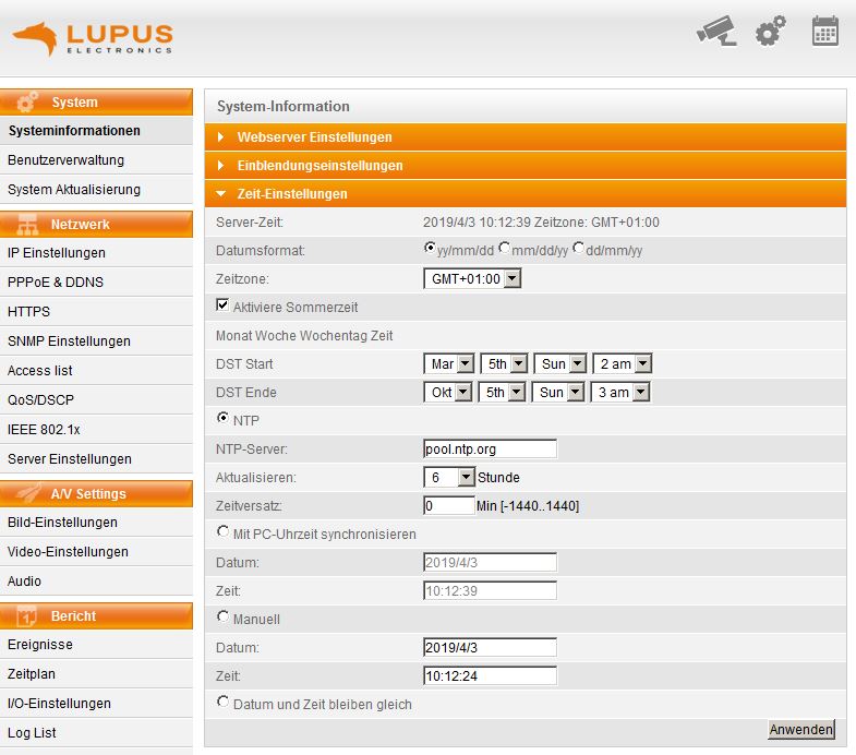
How do I correctly set-up the time / daylight saving time?
-
LE20x and recorder
Please use the following settings:
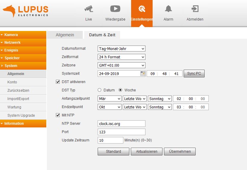
LE9xx cameras
Please use the following settings:
-
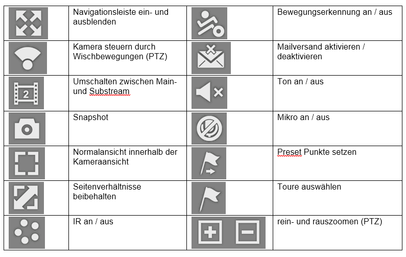
What is the function of the buttons in the iOS App?
-
Hier eine Auflistung der Symbole in der iOS App und deren Funktion:
-
The motion detection of my LUPUSNET HD camera does not work.
-
Please make sure that the following conditions are met:
- The three motion detection areas may not be too huge. Please use smaller areas in which a moving object is about half the hight of the set area
- Check if all three areas are enabled (if the left of the areas if checked)
- Increase the sensitivity of the motion detection
-
Videos(*.AVI) are saved with 0 KB on the NAS of my Fritz!Box.
-
In the Fritz.Nas there is a symbol of a storage device (USB stick). You need to create a new folder in this device and save the videos there.
-
Why can't I see the live stream of the camera / why does the camera plugin not work (64 bit browser)?
-
In case you do not see the live stream of the camera after you have installed the plugin and restarted the browser (open the browser with right click → execute as administrator), you should check if you use a 32 bit or 64 bit browser. Currently, the camera plugin is only optimised for 32 bit browsers and cannot be run by a 64 bit browser.
In case you use a 64 bit browser, you need to install a 32 bit browser.
-
The installation of LUPUSNET HD / SD-Downloader crashes (Windows XP).
-
Please install "Microsoft .NET Framework 4" first.
-
Why do I no longer get a live stream in my browser / Why is it no longer possible to install the plugin?
-
All of our cameras and recorders work without a plugin and display the videostream via html5. This means that you can use any modern browser to access your camera or recorder. We also have updates many of our older products that we no longer manufacture and sell.
Please check if you have the latest firmware of your product installed.:
Downloads for current products
Downloads for EOL products.In case your camera or recorder has not received a html5 update, you can still access it with Firefox ESR 52 (32 Bit), Internet Explorer 11 (32 Bit), and the 32 Bit-IE-Mode of the Edge browser.
Cameras LE 20x / 2xx
-
LE 20x / 2xx - How do I set up the motion detection correctly
-
The video is a brief manual (currently only in German).
In order to set up the motion detection of the LE 201 / LE 203 correctly, please proceed as follows:
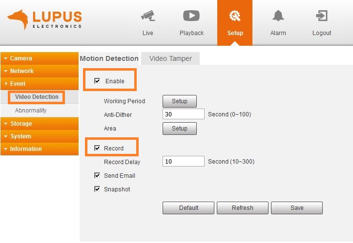
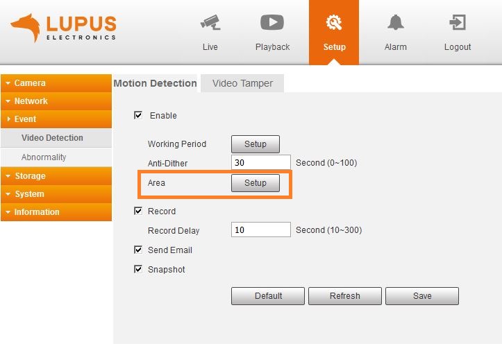
- Open the menu "Setup" → "Event" → "Video detection" → "Motion detection".
- Check the boxes next to "Enable" and "Record" in order to activate the motion detection and to trigger a video recording when a motion is detected.
- Click on "Setup" on the right of Area
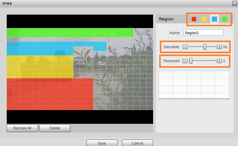
- You can mark up to four regions in different colours.
If an object moves in one of these regions, the motion detection can be triggered.
In order to filter which movements may trigger a motion detection, please use the controllers for sensitivity and threshold individually for each of the four regions.
Please note that a person who is closer to the camera (e.g. red area) requires a lesser sensitivity than a person who is further away (e.g. blue or green area) in order to trigger the motion detection.
In general, a higher sensitivity results in more motion detections and, a lower threshold results in more motion detections.
Click in the area menu, as well as, in the motion detection menu on "Save" to save your settings.
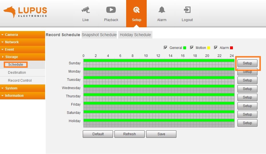
- Open the menu "Storage" → "Schedule" → "Record Schedule".
In this menu, allows you to setup when the camera will record and if it will be due to a motion detection (yellow marking) or a non-stop recording (green marking)
Click on "Setup" next to one of the days in the schedule
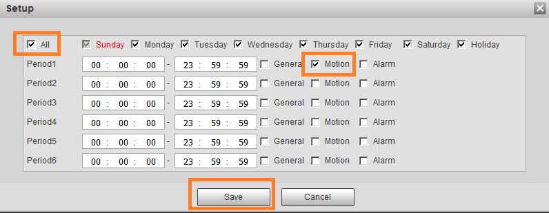
- Check the box next to "All" to make changes for all days of the week. Check the box next to "Motion" in order to set the schedule to motion detection for every day between 00:00:00 and 23.59.59.y
If the boxes next to "General" or "Alarm" are checked, you can uncheck them if you only want records that are triggered by the motion detection.
Click on "Save" in the menu "Setup", as well as, in the menu "Record Schedule" to save your new settings.
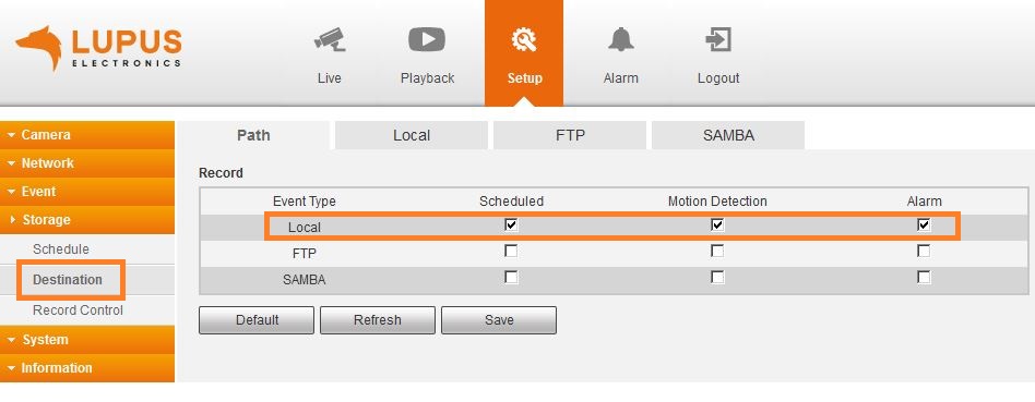
- In the menu "Storage" → "Destination", you can define where a recording should be saved. If you use an SD card in the camera, please select "Local" as destination and click on "Save".
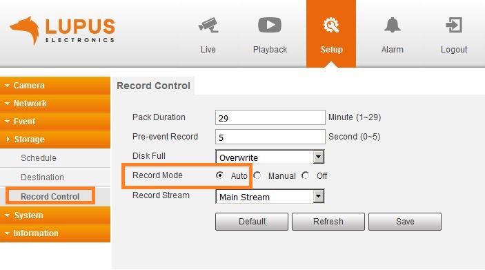
- Now you can check that the camera is set to make recordings according to the schedule. Open the menu "Storage" → "Record Control" and make sure that "Record mode" is set to "Auto".
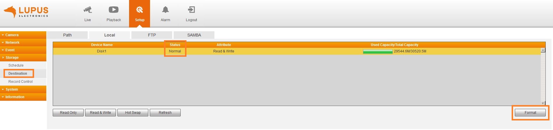
- Please also check that the camera correctly recognises your SD card your SD card. Open the menu "Storage" → "Destination" → "Local". In the column "Status" the SD card should be defined with "normal". If an error is indicated, please format the SD card via the "Format" option of the camera.
- Now, the camera begins to record if a motion is detected and the records are saved on the SD card.
-
LE 20x / 2xx - How can I find the IP address of my camera or my recorder using Windows 10?
-
Please download the latest version of our IP Finder for Windows. The latest version (at least 1.0.9) allows you to find the cameras LE 201 / LE 203, as well as, our recorders on a computer running Windows 10.
-
LE 20x / 2xx - How do I integrate the live stream of my camera into my XT alarm panel?
-
Since firmware 3.0 the XT features a network search option. Simply start the network search in the menu "Smarthome" → "Camera", select your camera, and enter username and password.
A video manual (currently only in German) can be found hier.
Old method
NO LONGER NECESSARY WITH LATEST FIRMWARE
Open the menu "Network" -> "Cameras" in your XT alarm panel.
Enter a name for the camera and the following link and fill in the place holders.http://USERNAME:PASSWORD@IP-ADDRESS-OF-THE-CAMERA:PORT/cgi-bin/mjpg/video.cgi?channel=0&subtype=1
Beginning with the firmware with built date (10.8.2018), the following command is also possible (required for Chrome / Opera):
http://IP-ADDRESSE:PORT/cgi-bin/mjpg/video.cgi?channel=0&subtype=1&user=BENUTZERNAME&password=PASSWORT
-
Is it possible to get a single JPG image from the recorder?
-
Yes, please use the following syntax:
Devices LE2xx V1 & V2 generation)
- https://username:password@IP-address/cgi-bin/snapshot.cgi?channel=1
Example with a standardised IP address, username and passwort:
- https://admin:admin@192.168.123.101/cgi-bin/snapshot.cgi?channel=1
Devices LE2xx V3 generation)
- https://username:password@IP-address/cgi-bin/snapshot.cgi?channel=1
Example with a standardised IP address, username and passwort:
- https://admin:admin@192.168.123.101/cgi-bin/snapshot.cgi?channel=1
-
LE 20x / 2xx - Activate or deactivate the motion detection schedule for your camera via your XT alarm panel.
-
Since firmware 3.0, the XT features this as a home automation action (menu "Smarthome" → "Automation"). Simply select your camera an define if you want to switch the motion detection on or off.
CGI-command
NO LONGER NECESSARY WITH LATEST FIRMWARE
Enter the following command into the action URL field of your alarm panel:- http://USERNAME:PASSWORD@IP-ADDRESS-OF-THE-LE201/cgi-bin/configManager.cgi?action=setConfig&MotionDetect[0].Enable=false
false = off
true = on
-
LE 232 - setting up the intelligent motion detection
-
The following video manual shows you how to correctly set up the intelligent motion detection of your LE 232 (currently only in German):
-
LE 232 - Richtig installiert für perfekte Personenerkennung
-
Damit die LE 232 Personen erkennt und Sie zufrieden sind, muss ein Mensch für die Kamera erkennbar sein.
Beachten Sie daher bei der Installation bitte folgenden Punkte:
- Neigungswinkel der Kamera:
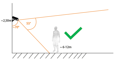
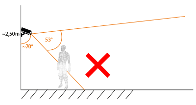
- Die optimale Installation hat einen Winkel von etwa 70° (+/- etwa 10%) zwischen Hauswand und Kamera – oder anders gesagt, die Kamera wird etwa 20° nach unten ausgerichtet.
Die Kamera sollte nicht stärker nach unten ausgerichtet werden, da dies dazu führt das Menschen, aufgrund der perspektivischen Verkürzung, für die Kamera nicht mehr optimal erkennbar sind.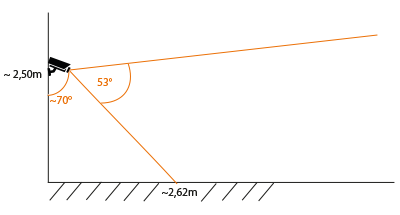
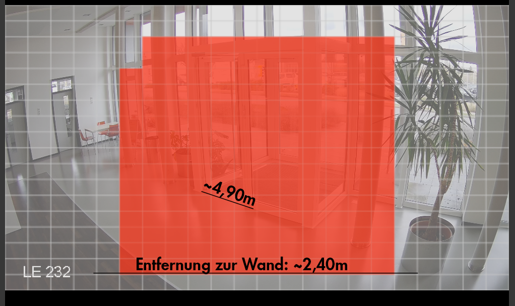
Die Entfernungswerte in Zeichnung und Bild sind unterschiedlich, da Installationshöhe und Neigung minimal vom Optimum abweichen. Aufgrund des vertikalen Blickwinkel der LE 232 (53°) muss eine Person also mindestens 2,40-2,62m von der Kamera entfernt sein, damit diese komplett (von Kopf bis Fuß) im Bild zu sehen ist.- Entfernung der Kamera zum Objekt:
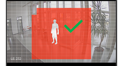
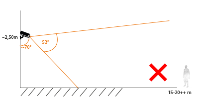
- Die optimale Erkennung eines Menschen findet im Bereich 6-12m vor der Kamera statt (eine Erkennung ist auch näher an der Kamera und weiter von der Kamera entfernt Möglich).
Ein Mensch oder Fahrzeug muss komplett im Erkennungsbereich der Kamera sein, darf diesen aber nicht zu mehr als zweidrittel ausfüllen (in Höhe und Breite).
Die maximale Entfernung, auf die wir in unserem Testaufbau einen Menschen erkannt haben, lag bei ~26 Metern- Person wird erkannt:
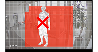
- Person ist zu groß (Erkennungsbereich wird komplett von der Person ausgefüllt):
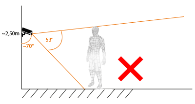
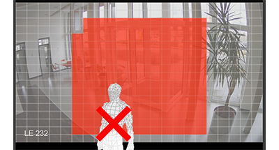
- Person ist zu Nahe / nicht komplett im Erfassungsbereich:
- Person zu weit entfernt / zu klein:
- Installationshöhe der Kamera:
- Die optimale Installationshöhe der Kamera ergibt sich aus dem Neigungswinkel und der Entfernung des zu überwachenden Bereichs. Bei den meisten Installationen wird eine Höhe von etwa 2,50m optimal sein.
Je höher die Kamera installiert wird, desto weiter müssen Objekte von der Kamera entfernt sein, damit diese korrekt erfasst werden können.
Vermeiden Sie eine zu hohe oder zu niedrige Installation, da es dann meist nicht mehr möglich ist, den optimalen Neigungswinkel und die Entfernung zum Objekt einzuhalten. - Neigungswinkel der Kamera:
-
LE 232 - Individual audio for the LE 232
-
Um eigene Audiodateien in der LE 232 abzuspeichern und zu verwenden, nutzen Sie bite folgende Anleitung:
Individuelle Audiodateien in LE 232 einspielen
-
LE 232 - Activate the LED floodlights for four seconds
-
https://Username:Password@IP-of-the-camera/cgi-bin/LupusAlarm.cgi?action=control&warning_light=4
The number behind "warning_light=" specifies how long you want to activate the floodlights (in seconds)
-
LE 232 - Play an audio file
-
https://Username:Password@IP-of-the-camera/cgi-bin/LupusAlarm.cgi?action=control&playAudio=10
The number behind "playAudio=" specifies which audio file is played.
-
LE 232 - Play audio file 4 and activate floodlights for four seconds
-
https://Username:Password@IP-of-the-camera/cgi-bin/LupusAlarm.cgi?action=control&playAudio=4&warning_light=4
The number behind "warning_light=" specifies how long you want to activate the floodlights (in seconds).
The number behind "playAudio=" specifies which audio file is played.
-
LE 232 - Activate the siren of the camera for five seconds
-
https://Username:Password@IP-of-the-camera/cgi-bin/LupusAlarm.cgi?action=control&siren=5
The number behind "siren=" specifies how long you want to activate the siren (in seconds - up to 99)
-
LE 213 - À quoi sert le voyant LED situé à l'avant de l'appareil photo ?
-
Vert fixe = Tout est OK. Vert clignotant rapidement = Le réseau est en cours de configuration. Vert clignotant lentement = Préparation de la configuration réseau. Rouge fixe = Démarrage. Rouge clignotant lentement = Échec de la connexion Wi-Fi. Vert et rouge clignotant en alternance = Mise à jour du micrologiciel. Éteint = Réinitialisation aux paramètres d'usine / pas d'alimentation.
-
LE 213 - Comment enregistrer certaines positions de caméra (positions préréglées) ?
-
Cela n'est possible que dans l'interface utilisateur Web de la caméra. Pour ce faire, ouvrez l'adresse IP de la caméra dans le navigateur. Si vous ne connaissez pas l'adresse IP, lancez l'outil IP Finder de LUPUS. Paramètres -> Fonction PTZ -> Préréglage 1. Déplacez-vous vers la position souhaitée. 2. Appuyez sur Ajouter 3. Appuyez sur Enregistrer. 4. Déplacez-vous vers la position suivante et appuyez à nouveau sur Ajouter et Enregistrer. Procédez ainsi pour tous les points.
-
Mon appareil photo redémarre et la carte SD n'est plus reconnue.
-
Les cartes SD normales ne sont pas adaptées aux enregistrements vidéo de longue durée, car elles génèrent des erreurs de bits lors de nombreux processus de stockage importants au cours d'une journée. Pour une utilisation dans des caméras de surveillance qui enregistrent fréquemment, il est préférable d'utiliser des cartes mémoire MAX ou HIGH ENDURANCE, telles que celles proposées par Sandisk.
-
LE 281 - Which PoE switch is required?
-
The LE 281 requires a PoE+ switch (according to IEEE 802.3at). A PoE switch according to IEEE 802.3af does not supply enough power for this camera.
-
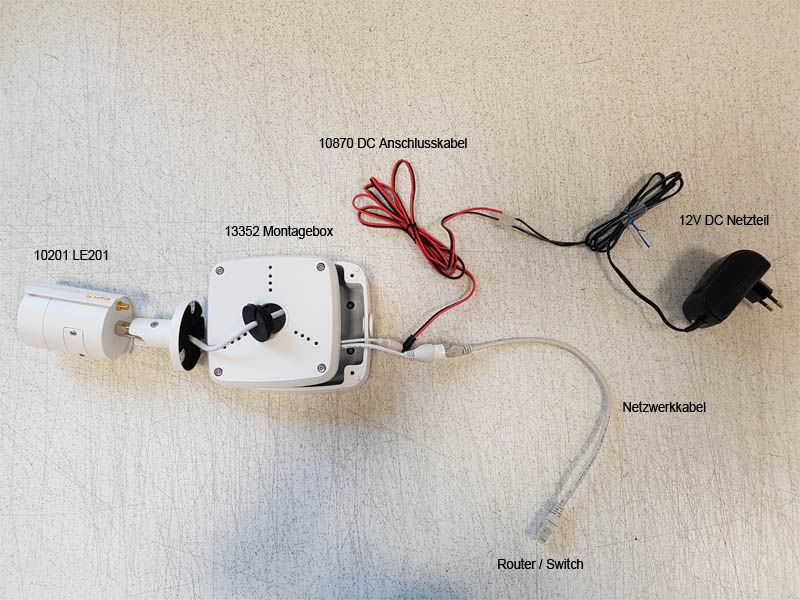
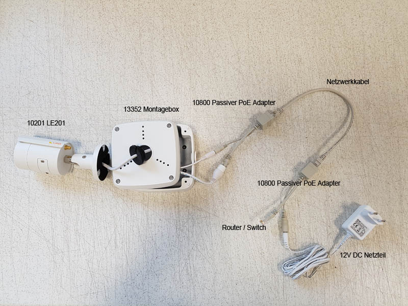
Wie wird die Kamera möglichst professionell installiert?
-
Mit unseren Zubehörartikeln wie Montagebox, DC-Anschlusskabeln sowie PoE Adaptern können Sie unsere Kameras professionell, wetterfest und ohne sichtbare Kabel installieren.
Variante 1
Variante 2
-
LE 20x / 2xx - Wie kann ich über die Alarmanlage Aufnahmen der Kamera starten?
-
Seit Firmware 3.0 verfügt die XT über eine entsprechende Automations-Aktion (Menü "Smarthome" → "Automation"). Dort können Sie Ihre IP Kamera wählen und eine Aufnahme starten (manuelle Aufnahme) oder stoppen (Zeitplan einhalten)
CGI-Befehl
MIT AKTUELLER FIRMWARE NICHT MEHR NOTWENDIG
1. Erstellen Sie in der XT eine Automationsregel.
2. Geben Sie als Aktion "Action-URL" an.
3. Verwenden Sie folgenden Befehl zum Aufnahmestart ("manuelle" Daueraufnahme):http://Benutzername:Passwort@IP-ADRESSEderKAMERA:PORT/cgi-bin/configManager.cgi?action=setConfig&RecordMode[0].Mode=1
4. und eine zweite Regel zum Aufnahme stoppen ("aus" - keine Aufnahmen mehr):
http://Benutzername:Passwort@IP-ADRESSEderKAMERA:PORT/cgi-bin/configManager.cgi?action=setConfig&RecordMode[0].Mode=2Alternativ können Sie zum Ausschalten auch folgenden Befehl verwenden:
http://Benutzername:Passwort@IP-ADRESSEderKAMERA:PORT/cgi-bin/configManager.cgi?action=setConfig&RecordMode[0].Mode=0
Damit stellen Sie die Kamera in den automatischen Modus und der in der Kamera hinterlegte Aufnahmezeitplan wird eingehalten.
-
LE 20x / 2xx - Email Funktion per Automationsregel aktivieren / deaktivieren
-
Seit Firmware 3.0 verfügt die XT über eine entsprechende Automations-Aktion (Menü "Smarthome" → "Automation"). Dort können Sie Ihre IP Kamera w&auhlen und die E-Mail Benachrichtigung ein oder ausschalten
CGI-Befehl
MIT AKTUELLER FIRMWARE NICHT MEHR NOTWENDIG
1. Erstellen Sie in der XT eine neue Automationsregel.
2. Geben Sie als Aktion "Action-URL" an.
3. Verwenden Sie folgenden Befehl um die Email-Funktion zu aktivieren:
AKTIVIEREN
http://Benutzername:Passwort@IP-ADRESSEderKAMERA:PORT/cgi-bin/configManager.cgi?action=setConfig&MotionDetect[0].EventHandler.MailEnable=true
DEAKTIVIEREN:
http://Benutzername:Passwort@IP-ADRESSEderKAMERA:PORT/cgi-bin/configManager.cgi?action=setConfig&MotionDetect[0].EventHandler.MailEnable=false
-
What is the function of the buttons in the iOS App?
-
Hier eine Auflistung der Symbole in der iOS App und deren Funktion:
-
LE 20x / 2xx - How do I perform a factory reset ?
-
Einen Hardware Reset inklusive Löschen aller Einstellungen und Benutzer / Passwörter erfolgt folgendermaßen:
- Entfernen Sie die Abdeckung des SD-Kartenslots an der Kamera (bei der LE203 ist der Knopf an der Hinterseite).
- Drücken Sie im laufenden Betrieb den Knopf neben dem SD-Kartenslot für etwa 15 Sekunden.
- Sobald die grüne und die rote LED neben dem SD Kartenslot anfangen zu blinken können Sie den Knopf wieder loslassen.
- Die Kamera führt nun den Reset durch (LEDs blinken weiterhin)
- Nach etwa zwei Minute leuchtet die grüne LED und die Kamera ist wieder erreichbar.
-
What does error code #2154 indicate?
-
Error code #2154 indicates that the mainstream cannot be displayed since the mainstream is set to MJPEG.
Please set the compression of the mainstream to H.264, H.264B, or H.264H in the menu "Settings" → "Camera" → "Video".
If you have integrated the camera into your XT alarm panel, please make sure that the command ends with subtype=1". Otherwise, the XT would switch the mainstream back to MJPEG.
-
LE 203 - How can I activate and deactivate the audio detection?
-
Use the following command to activate the audio detection:
http://USERNAME:PASSWORD@IP-ADDRESS:PORT/cgi-bin/configManager.cgi?action=setConfig&AudioDetect[0].MutationDetect=trueUse the following command to deactivate the audio detection:
http://USERNAME:PASSWORD@IP-ADDRESS:PORT/cgi-bin/configManager.cgi?action=setConfig&AudioDetect[0].MutationDetect=false
-
How can I display my camera / recorder in Echo Show?
-
Um unsere Kameras und Rekorder auch in Ihrem Alexa / Echo Show anzeigen zu können, gehen Sie bitte folgendermaßen vor:
Bei einem "Echo Show 5" wird von Monocle ein Gateway benötigt. Hier finden Sie die offizielle Angabe von Monocle cam zu dieser Thematik.
- Als erstes müssen Sie sich auf der Website www.monoclecam.com ein Konto erstellen (mittels "Register now")
- Nach der Registrierung erhalten Sie noch eine E-Mail auf der von Ihnen verwendeten Adresse. In dieser müssen Sie noch einmal bestätigen, dass Sie das Konto anlegen möchten.
Wenn Sie sich dann per "Sign in" Angemeldet haben, sehen Sie folgende Oberfläche: - Durch klicken auf "Add camera feed" erscheint folgende Eingabemaske:
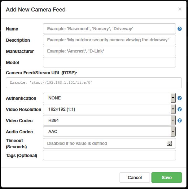
- Name: Name Ihrer Kamera (Rufname für Alexa)
- Description: Beschreibung um die Kamera besser zuordnen zu können
- Manufacturer: LUPUS-Electronics
- Model: LE 201
- Camera Feed/Stream URL (RTSP): rtsp://192.168.0.43:554/cam/realmonitor?channel=1&subtype=0
IP Adresse auf die Ihrer Kamera anpassen - Authentication: DIGEST
- Username: Benutzername Ihrer Kamera
- Password: Passwort Ihrer Kamera
- Video Resolution: "1280x720 (16:9) [HD] <720p>" (bzw. die Auflösung auf welche Sie die Kamera eingestellt haben.
- Audio Codes: "G711" (nur bei LE 203)
- Name: Name Ihrer Kamera (Rufname für Alexa)
- Description: Beschreibung um die Kamera besser zuordnen zu können
- Manufacturer: LUPUS-Electronics
- Model: LE 201
- Camera Feed/Stream URL (RTSP): rtsp://192.168.0.43:554/cam/realmonitor?channel=1&subtype=0
IP Adresse auf die Ihrer Kamera anpassen - Authentication: DIGEST
- Username: Benutzername Ihrer Kamera
- Password: Passwort Ihrer Kamera
- Video Resolution: "1920x1080 (16:9) [FHD] <1080P>" (bzw. die Auflösung auf welche Sie die Kamera eingestellt haben.
- Audio Codes: AAC (nicht relevant da kein Audio möglich)
- Name: Name Ihres Rekorders (Rufname für Alexa)
- Description: Beschreibung um die Kamera besser zuordnen zu können
- Manufacturer: LUPUS-Electronics
- Model: LE 808 HD V2 (bzw. passender Name des Rekorders)
- Camera Feed/Stream URL (RTSP): rtsp://192.168.0.43:554/cam/realmonitor?channel=1&subtype=0
IP Adresse auf die Ihres Rekorers anpassen - Authentication: DIGEST
- Username: Benutzername Ihrer Kamera
- Password: Passwort Ihrer Kamera
- Video Resolution: Die Auflösung auf welche Sie die Kamera eingestellt haben.
- Audio Codes: "G711"
- Name: Name Ihres Rekorders (Rufname für Alexa)
- Description: Beschreibung um die Kamera besser zuordnen zu können
- Manufacturer: LUPUS-Electronics
- Model: LE 926 4K (bzw. passender Name des Rekorders)
- Camera Feed/Stream URL (RTSP): rtsp://192.168.0.43:554/cam/realmonitor?channel=1&subtype=0
IP Adresse auf die Ihres Rekorers anpassen - Authentication: DIGEST
- Username: Benutzername Ihrer Kamera
- Password: Passwort Ihrer Kamera
- Video Resolution: Die Auflösung auf welche Sie die Kamera eingestellt haben.
- Audio Codes: "G711"
- Als nächstes müssen Sie in Ihrer Alexa App nach dem "monocle" Skill suchen und diesen aktivieren.
Nach der Aktivierung müssen Sie die E-Mailadresse und das Passwort eingeben, mit welchem Sie sich auch www.monoclecam.com registriert hatten. - Wenn der Skill erfolgreich hinzugefügt wurde, klicken Sie links oben auf "Fertig" und beim Fenster danach können Sie auf "Geräte erkennen" klicken (dies dauert etwa 20 Sekunden).
- Der Monocle Skill wird Ihnen nun alle Kameras anzeigen, welche Sie Ihrem Monocle Konto hinzugefügt haben.
- An Ihrem Alexe / Echo Show können Sie nun durch Sprachbefehl "Alexa zeige Kamera [Kameraname]" Ihre Kamera Aufrufen und mittels "Alexa beendet Kamera [Kameraname] die Livebildwiedergabe beenden"
Für unsere Beispiele oben wären die Befehle also:- Zum Starten:
- "Alexa zeige Kamera Eingang"
"Alexa zeige Kamera Garage"
"Alexa zeige Kamera Garten"
usw.- "Alexa Beendet Kamera Eingang"
"Alexa Beendet Kamera Garage"
"Alexa Beendet Kamera Garten"
usw.
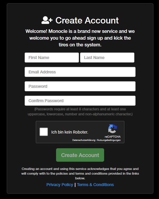
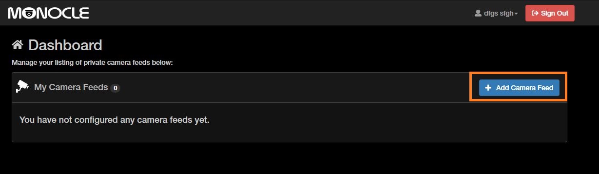
- LE 201 / 203:
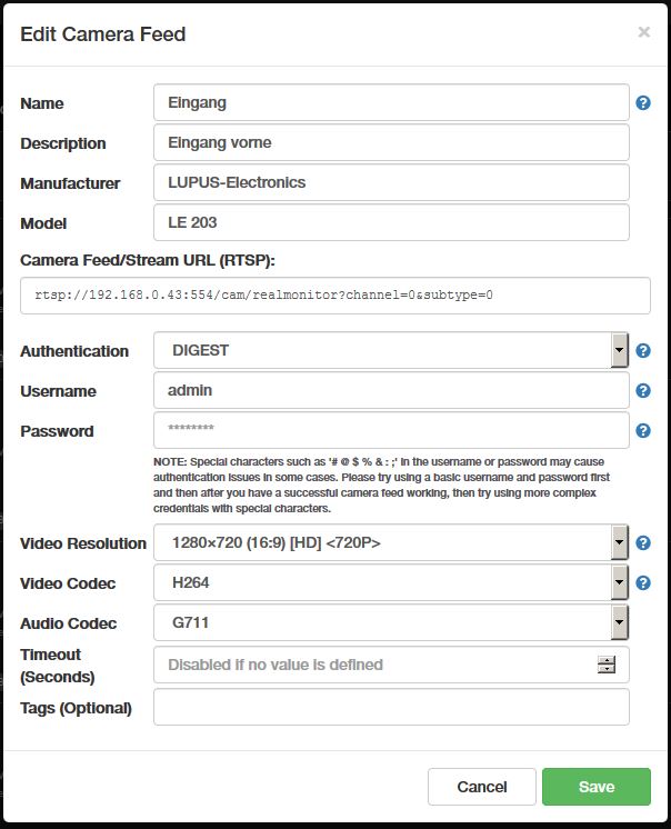
- LE 202 / 204:
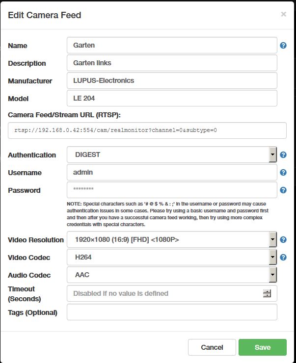
- HDTV Rekorder
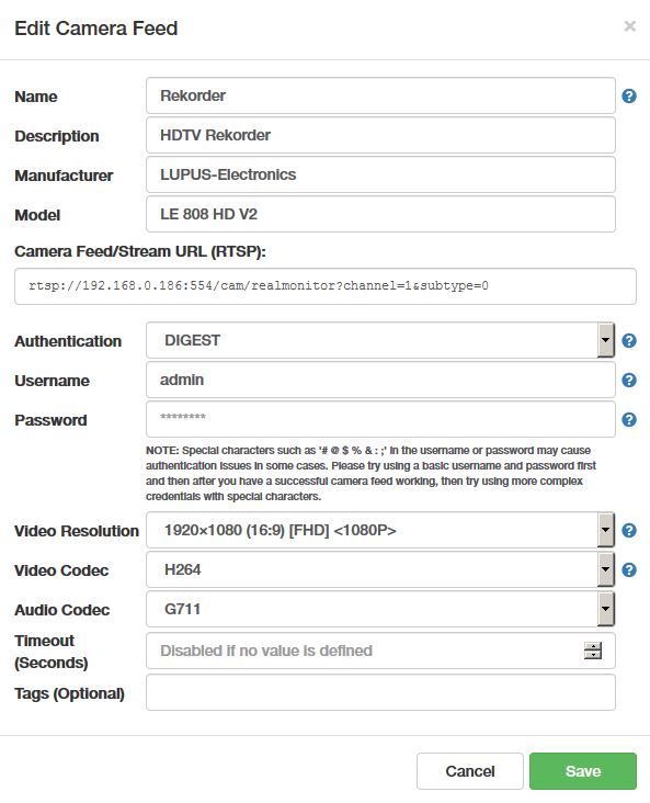
- NVR
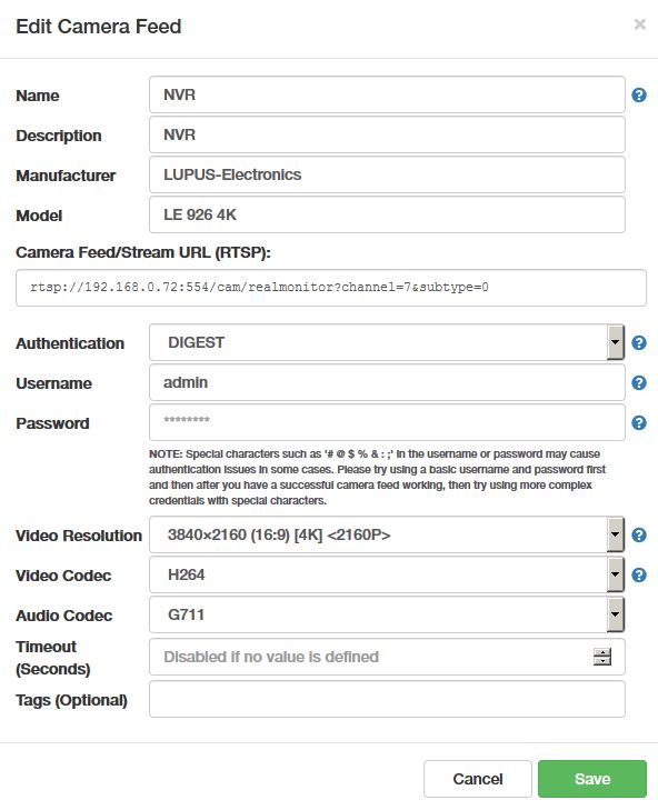
-
Pourquoi je ne peux pas intégrer la caméra via ONVIF ?
-
Toutes les caméras LUPUS prennent en charge ONVIF via HTTP et HTTPS. Toutes les caméras LUPUS utilisent une connexion sécurisée (HTTPS) et redirigent automatiquement vers HTTPS si l’on tente d’y accéder via HTTP. Cependant, la plupart des solutions tierces, comme Synology, Ubiquiti ou d’autres, ne peuvent établir qu’une connexion ONVIF non chiffrée. Désactivez donc d’abord, dans l’interface web (WebUI) de la caméra LUPUS, la redirection automatique vers HTTPS, puis, après le redémarrage qui s’ensuit, désactivez également le chiffrement HTTPS. L’intégration dans un logiciel tiers devrait alors fonctionner.
Cameras LE 9xx (EOL)
-
LE 9xx camera - How do I set up the motion detection?
-
Wie richte ich die Bewegungserkennung auf meiner Kamera LUPUSNET HD - LE 9xx richtig ein?
Um die Bewegungserkennung Ihrer LE 9xx Kamera einzurichten, öffnen Sie bitte die das Webinterface der Kamera.
Falls Sie auch einen NVR besitzen, richten Sie die Bewegungserkennung bitte über diesen ein – eine Anleitung finden Sie unter der FAQ: "LUPUSTEC - Rekorder - NVR - Wie richte ich die Bewegungserkennung auf meinem NVR richtig ein?"- Klicken Sie nun oben rechts auf die Zahnräder um in die Einstellungen der Kamera zu gelangen.
- Öffnen Sie das Untermenü "Bericht" → "Ereignisse".
- Mittels der Schaltflächen "Bereich 1", "Bereich 2" und "Bereich 3" können Sie drei Bereiche im Livebild (im oberen Bereich dieses Fensters) markieren in welchen die Bewegungserkennung stattfinden soll
Die Einstellung "Empfindlichkeit" erlaubt Ihnen Festzulegen wie Sensibel die Bewegungserkennung reagieren soll. Je nach Kameramodell können Sie diese für jeden Bereich individuell Einstellen oder für alle Bereiche zusammen. - Drücken Sie nun auf "Anwenden" um die Einstellungen zu übernehmen.
- Wird eine Bewegung erkannt, wird Ihnen nun im kleinen Livebild oben rechts "Motion" angezeigt.
Zusätzlich wird jede Bewegung als Balkendiagramm im unteren Bereich angezeigt. Sobald der Ausschlag eines Balkens über der roten Linie liegt (diese Zeigt die Beschränkung des aktuell unter dem Diagramm ausgewählten Bereiches an), wird diese Bewegung von der Kamera als eine relevante Bewegung erkannt. Mittels dieses Diagramms können Sie also die "Empfindlichkeit" und "Beschränkung" auf Ihre individuelle Situation anpassen.
- Je höher die "Empfindlichkeit" desto mehr Aufnahmen gibt es.
Die Einstellung "Beschränkung" erlaubt Ihnen einen Wert festzulegen welcher erreicht werden muss damit eine Bewegung erkannt wird. Je nach Kameramodell können Sie diese für jeden Bereich individuell Einstellen oder für alle Bereiche zusammen.- Je höher die "Beschränkung" desto weniger Aufnahmen gibt es.
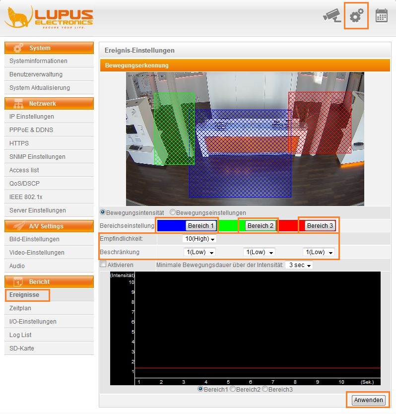
- Klicken Sie nun unter dem kleinen Livebild auf "Bewegungseinstellungen".
- In diesem Menü können Sie definieren, was bei einer erkannten Bewegung geschehen soll.
- Damit die von Ihnen eingestellten Bereiche aktiv sind, ist es notwendig, dass Sie in diesem Menü die Haken bei den jeweiligen Bereichen setzen.
- Rechts der einzelnen Bereiche können Sie wählen auf welchem Medium die Kamera eine Aufnahme speichern soll (um E-Mail, FTP und Samba zu nutzen, müssen diese über das jeweilige Menü definiert werden).
- Soll die Bewegungserkennung nur zu bestimmten Zeiten aktiv sein, setzen Sie noch den Haken bei "Gemäß Zeitplan".
- Unter "Dateiaufzeichnung" können Sie einstellen ob die Kamera ein AVI Video speichern soll oder ob diese einen Schnappschuss machen soll - hier ist nur eines der beiden möglich.
- Wenn Sie eine Videoaufzeichnung machen, können Sie wählen wie viele Sekunden vor und nach der Bewegung die Kamera speichern soll.
Der Voralarm kann zwischen 0 und 5 Sekunden eingestellt werden, der Nachalarm Modellabhängig zwischen 0 und 10 bzw. 0 und 15 Sekunden. - Klicken Sie danach ganz unten auf der Seite auf "Anwenden".
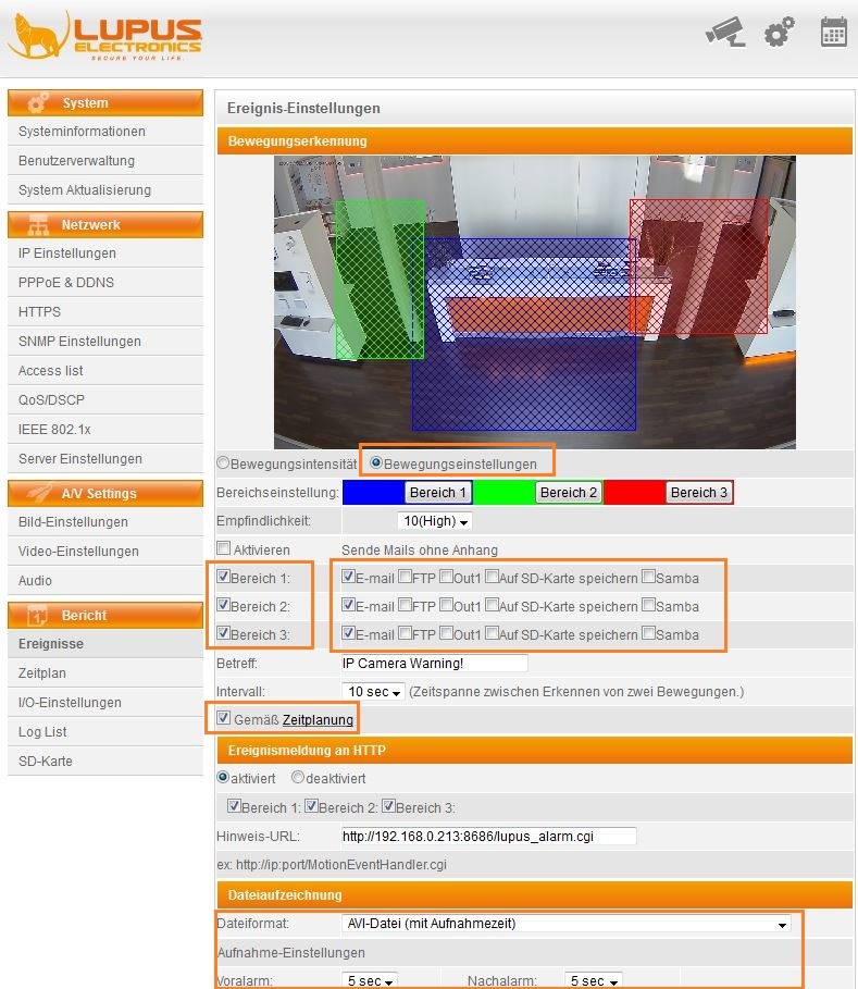
- Sollten Sie "Gemäß Zeitplan" aktiviert haben, gehen Sie nun noch in das Menü "Bericht" → "Zeitplan".
- Sie können die Kamera an jedem Tag individuell aktivieren oder deaktivieren. Markieren Sie die Stunden zu denen die Bewegungserkennung der Kamera aktiv sein soll grün.
- Achten Sie bitte darauf, dass "Zeitplan deaktiviert" ausgewählt ist. Mittels dieser Option kann man den Zeitplan für andere Arten der Aufzeichnung nutzen - dies wird für die Bewegungserkennung aber nicht benötigt.
- Klicken Sie nun auf "Anwenden".
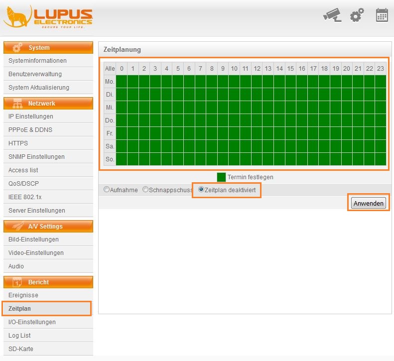
-
LE 9xx camera - How can I connect my LE9xx IP camera with my XT alarm panel?
-
Since firmware 3.0 the XT features a network search option. Simply start the network search in the menu "Smarthome" → "Camera", select your camera, and enter username and password
A video manual (currently only in German) can be found hier.
Old method
NO LONGER NECESSARY WITH LATEST FIRMWARE
You can integrate the live stream of your IP camera into the XT alarm panel with the following command:- http://username:password@MyCamera.lupus-ddns.de:PORT/GetData.cgi?CH=02
You can also use the following command to send username and password as a parameter (some browsers require this syntax):
http://MyCamera.lupus-ddns.de:Port/GetData.cgi?CH=02&usr=USERANME&pwd=PASSWORD- username - Username of the camera
- password - Password of the camera
- MyCamera.lupus-ddns.de - please insert your DDNS address or the local IP address of the camera here
- Please note: if you choose the local IP address, the live stream can only be displayed while you are connected with your local network.
- 1000 - please insert the external port you selected for the port forwarding of the camera in your router (only access via DDNS) or the local port of the camera (only local access).
Please note: Streaming 2 needs to be activated in the video settings of the camera.
Please note: the live stream cannot be displayed in Internet Explorer.
Please note: The LUPUSNET HD - LE200 requires a different command:
- http://IP-AdresseLE200:PORT/cgi-bin/CGIStream.cgi?cmd=GetMJStream&usr=USERNAME&pwd=PASSWORD
You can integrate any IP camera that has an MJPEG stream. Please contact the manufacturer of your camera to ask for the required command to access this stream.
-
LE 923, 924, 931, 932, 933, 934, 936 - How do I restore the factory default of my IP camera?
-
In order to completely reset (factory default) your IP camera, please use the following instructions:
- Disconnect the camera from its power source and from the ethernet cable
- Bridge GND and Default on the terminal strip
- Connect the camera again to a power source
- The camera requires about one minute to reset while it is powered and GND and default are bridged
- After one minute, you can disconnect the camera again from its power source and remove the bridging
- After you have connected the camera again with your network, the camera will have the static IP address 192.168.1.200
-
LE 966, 967, 968, 969, 971, 981, 982 - How do I restore the factory default of my IP camera?
-
In order to completely reset (factory default) your IP camera, please use the following instructions:
- Disconnect the camera from its power source and from the ethernet cable
- Press an hold the reset button in the camera
- Connect the camera again to a power source
- Hold the reset button for about one minute while the camera is connected to a power source
- After one minute, you can disconnect the camera again from its power source and stop to hold the reset button
- After you have connected the camera again with your network, the camera will have the static IP address 192.168.1.200
-
LE 9xx camera - The night-vision quality is bad. How can I imporve it?
-
Please set SensUp in the menu 'Image settings' to 1/5 and make sure that there are no objects (e.g. branches, tress) too close to the camera.
-
LE 971 - How can I adjust the zoom and focus?
-
There are two screws that allow you to adjust the zoom and focus of the LE 971:
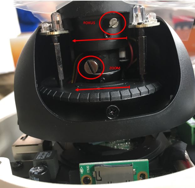
-
LE936 Plus - Zoom über die Alarmanlage steuern (.cgi)
-
http://user:pw@IP:Port/SetPTZ.cgi?Dir=ZoomOut
-
Le 9xx camera - E-Mail Versand über LUPUSEC XT aktivieren / deaktivieren.
-
Erstellen Sie eine neue Automationsregel und geben Sie dort den folgenden, angepassten Pfad zu Ihrer LUPUSNET HD Kamera an (nicht für LE200/201):
http://BENUTZERNAME:PASSWORT@IP-Adresse:PORT/SetMail.cgi?Mail_Enable=1
http://BENUTZERNAME:PASSWORT@IP-Adresse:PORT/SetMail.cgi?Mail_Enable=0 Weitere Befehle:
SetTrigger.cgi
SetMail.cgi?Mail_Enable=1
SetFTP.cgi?FTP_Enable=1
SetSamba.cgi?SMB_Enable=1
GetInputOsd.cgi
SetInputOsd.cgi
SetSamba.cgi
-
LE 9xx Kamera - Was für Mikrofone nutzen die Kameras aus der LUPUSNET Serie?
-
Man benötigt ein Computermikrofon mit entweder einem 3.5 mm Klinke oder Cinch Anschluß (je nach Kameratype) mit folgenden Werten: Impedanz von 2.2K Ohm, Eingangspegel 1 Vrms, Aktives Mikrofon mit eingebautem Verstärker, Frequenzbereich 20 ~ 100,00Hz.
-
LE 9xx camera - Why does my 9xx camera registers motions non-stop?
-
Please make sure that the latest version of the plugin is installed.
To install the latest version, delete the old plugin beforehand. THe old plugin can be found in the following directory:
32 bit sstem:
C:\Windows\System32\WebWatch2
64 bit system:
C:\Windows\SysWOW64\WebWatch2If the plugin cannot be found in these folders, please contact our technical support in order to allow them to delete the plugin correctly.
Cameras LE 200 (EOL)
-
How do I integrate the live stream of my LE200 into my XT alarm panel?
-
In order to integrate the live stream of you LE200 into the XT alarm panel, you need to install the latest firmware update of the camera and set the sub-stream compression to MJPEG
Please use the following command to integrate the camera:
- http://IP-ADRESSLE200:PORT/cgi-bin/CGIStream.cgi?cmd=GetMJStream&usr=USERNAME&pwd=PASSWORD
-
Why can't I control my LE 200 in the LUPUSEC App?
-
In der App ist die Steuerung der LE 200 standardmäßig deaktiviert – sowohl bei Integration in die XT und in einem eigenen Profil nur für die Kamera.
Bitte klicken Sie in das Livebild der Kamera und verwenden Sie folgende Option um die Steuerung der Kamera zu aktivieren oder zu deaktivieren: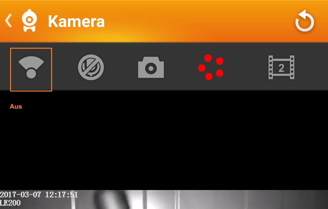
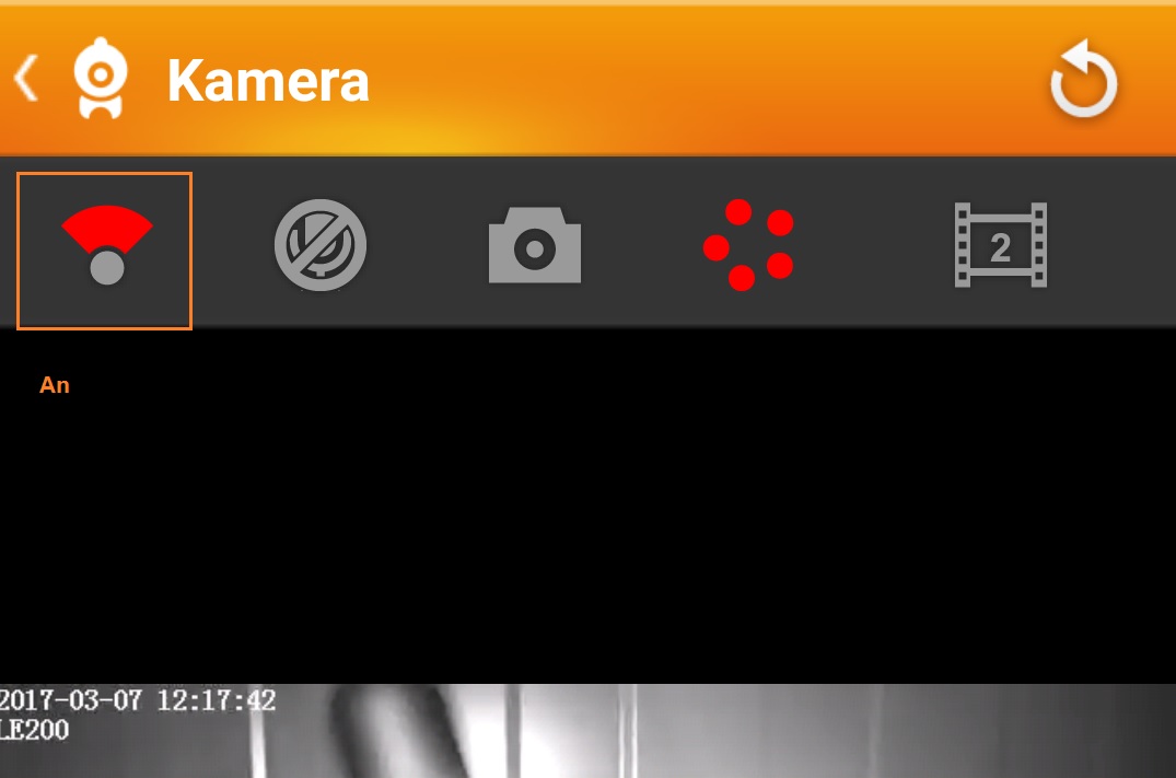
-
How do I connect the camera LE200 to a NVR?
-
Um die LE 200 richtig in unsere NVRs einzubinden, verwenden Sie bitte folgende Einstellungen:
Hersteller Generell URL Adresse rtsp://IPAdresse-der-Kamera:http-Port/videoMain
z.B.: rtsp://192.168.0.206:80/videoMainBenutzername Loginbenutzername der Kamera Passwort Loginpasswort der Kamera Decode Buffer Default Server Type Zeitplan
-
I cannot control my LE200 with my browser.
-
The integrated browser protection of some virus scanners (e.g. Mcafee) can influence the control of the LE200. In this case it is necessary to deactivate the browser protection of your virus scanner.
-
How do I get a JPG of camera?
-
Use this Command:
http://IP-ADR:PORT/cgi-bin/CGIProxi.fcgi?cmd=snapPicture2&usr=XXXXX&pwd=XXXXX
-
Does the LE200 record audio, as well as video?
-
The LE200 does not record audio.
-
LE200 does not work with google Chrome.
-
Please install the latest firmware of the camera.
-
What is the RTSP command of the camera?
-
rtsp://username:pwd@IP:port/videoMain
rtsp://username:pwd@IP:port/videoSub
rtsp://username:pwd@IP:port/audio
-
MacOS - The live stream of the LE200 does not show
-
Please access the camera with your safari browser and download the plugins.pkg.
To install the plugins.pkg, you need to ctrl click the file or open it via the context menu with the right mouse button.
-
What are the default user and password of my LE 200 camera?
-
There is no default user and password set. When you access the camera for the first time, you are asked to set a user and a password.
You may not name the new user "admin"
-
How can I control the motion detection via an action url command of the XT?
-
Mit folgendem Befehl können Sie die Bewegungserkennung der LE 200 ein- und ausschalten. Für die Action URL ist mindestens Firmware 2.18N auf der XT notwendig.
Einschalten:http://IP-Adresse:Port/cgi-bin/CGIProxy.fcgi?cmd=setMotionDetectConfig&isEnable=1&linkage=8&sensitivity=2&schedule0=281474976710655&schedule1=281474976710655&schedule2=281474976710655&schedule3=281474976710655&schedule4=281474976710655&schedule5=281474976710655&schedule6=281474976710655&usr=admin&pwd=Passwort
Beim Einschalten muss die Sensitivität im Befehl korrekt eingestellt werden:
- 0 = niedrig
- 1 = mittel
- 2 = hoch
- 3 = niedriger
- 4 = sehr niedrig
Ausschalten:
http://IP-Adresse:Port/cgi-bin/CGIProxy.fcgi?cmd=setMotionDetectConfig&isEnable=0&usr=Benutzername&pwd=Passwort
Recorder General
-
Why do I no longer get a live stream in my browser / Why is it no longer possible to install the plugin?
-
All of our cameras and recorders work without a plugin and display the videostream via html5. This means that you can use any modern browser to access your camera or recorder. We also have updates many of our older products that we no longer manufacture and sell.
Please check if you have the latest firmware of your product installed.:
Downloads for current products
Downloads for EOL products.In case your camera or recorder has not received a html5 update, you can still access it with Firefox ESR 52 (32 Bit), Internet Explorer 11 (32 Bit), and the 32 Bit-IE-Mode of the Edge browser.
-
Why can't I see the live stream of the camera / why does the camera plugin not work (64 bit browser)?
-
All of our cameras and recorders work without a plugin and display the videostream via html5. This means that you can use any modern browser to access your camera or recorder. We also have updates many of our older products that we no longer manufacture and sell.
Please check if you have the latest firmware of your product installed.:
Downloads for current products
Downloads for EOL products.In case your camera or recorder has not received a html5 update, you can still access it with Firefox ESR 52 (32 Bit), Internet Explorer 11 (32 Bit), and the 32 Bit-IE-Mode of the Edge browser.
In case you do not see the live stream of the camera after you have installed the plugin and restarted the browser (open the browser with right click → execute as administrator), you should check if you use a 32 bit or 64 bit browser. Currently, the camera plugin is only optimised for 32 bit browsers and cannot be run by a 64 bit browser.
In case you use a 64 bit browser, you need to install a 32 bit browser.
-
Why can\'t I access my recorder via webbrowser / SmartVision software?
-
We ship our recorder with a static IP addrss (192.168.1.108). You need to adjust the IP address in order to gain access to the recorder with your computer.
In order to do that, you require a mouse and a monitor that is connected directly to the recorder.
1. Rightclick to open the context menu and select Main menu.
2. Open the menu Network in the row Setting.
3. Select DHCP or asign a fixed IP address in the submenu TCP/IP.
4. Click on Apply and then on OK to save the changes
The new IP address will now be set and you can connect to the recorder via the webbrowser of you computer.
-
How can I find the IP address of my camera or my recorder using Windows 10?
-
Please download the latest version of our IP Finder for Windows. The latest version (at least 1.0.9) allows you to find the cameras LE 201 / LE 203, as well as, our recorders on a computer running Windows 10.
-
What is the function of the buttons in the iOS App?
-
Hier eine Auflistung der Symbole in der iOS App und deren Funktion:
-
I cannot login into my HDTV / NVR Rekorder. (Login error - Invalid password)
-
1. Close your browser
2. Run the install program in the following directory (64 bit system):
- C:\Program Files (x86)\webrec\WEB30\WebPlugin
Run the install program in the following directory (32 bit system):- C:\Program Files\webrec\WEB30\WebPlugin
3. Open the recorder again in your browser
4. Install the plugin
-
Login error after too many login attempts with a wrong user / password.
-
After 5 login attempts with a wrong password, the recorder locks this account.
You need to restart the recorder to unlock the account again.
In the latest firmware, the account will automatically be unlocked after 30 minutes
-
Since I updated the Firmware I can no longer log into my recorder.
-
The recorder needs to install a new version of the plugin. The old one needs to be uninstalled manually.
You can find the uninstall program in the following directory (64 bit system):
C:\Program Files (x86)\webrec\WEB30\WebPluginYou can find the uninstall program in the following directory (32 bit system):
C:\Program Files\webrec\WEB30\WebPlugin
-
How much storage space do I need?
-
Please note that these are estimated record times for a continuous recording. However, the record time of a continuous recording is influenced by the amount of movement in the image - the more movement there is, the more storage space is required.
Thus, these times can only serve as an indication of the storage space you might require.
The record time is estimated for one camera with 25 frames per second.
Resolution Storage space Estimated record time 720p 32Gb 21 Stunden 1Tb 28 Tage 1080p 32Gb 9 Stunden 1Tb 12 Tage 4K 32Gb 2 Stunden 1Tb 3 Tage
-
Wie kann ich den Email-Versand meines Rekorders per Action URL aktivieren/deaktivieren?
-
Mit dieser URL kann der Email-Versand des Rekorders aktiviert und deaktiviert werden. Zum Aktivieren wird der Wert "true" und zum deaktivieren der Wert "false" übergeben.
http://admin:admin@192.168.x.x/cgi-bin/configManager.cgi?action=setConfig&Email.Enable=false
-
Required port forwardings for an access via internet
-
You need to open three ports to access your recorder.
The default web port (TCP 80) can be forwarded from any external port of your choice
The following ports need to be forwarded from identical ports:
- 1. TCP 37777 to TCP 37777
- 2. UDP 37778 to UDP 37778
-
Internet Explorer crashes as soon as I access the recorder via network or internet.
-
Please add the IP-/ DDNS address of the recorder to the list of trustworthy sites of your virus scanner
Recorder NVR
-
How do I display the stream of my LE9xx 4K recorder in my XT alarm panel?
-
Use the following command in the XT:
http://IP-ADRESs:PORT/cgi-bin/mjpg/video.cgi?channel=1&subtype=1&user=USERNAME&password=PASSWORD
"Channel" allows you to choose the camera. Please use the channel number of the camera -1Set the frame itnervall of the second stream to 1sec in the recorder
-
How do I set up the motion detection on my NVR?
-
Bewegungserkennung richtig Einstellen (NVR Rekorder)
Um die Bewegungserkennung der über einen Rekorder richtig einzurichten sind mehrere Schritte notwendig.
- Überprüfen Sie bitte zuerst ob auf Ihrer Kamera eine ältere Firmware installiert ist. Bei älteren Firmware Versionen ist es notwendig ein Firmware Update durchzuführen:
V(A) vor 1.0.50
VB vor 1.0.46
VC vor 1.0.24 - Im Menü "Einstellung" → "Suche" → "Suche" müssen alle Kameras mit dem Herstellerprotokoll LUPUS hinterlegt sein (bei der Kamera LE 201 kann das Privat Protokoll verwendet werden).
- Im Menü "Einstellung" → "Ereignis" → "Bewegung" → "Bewegung" müssen Sie nun die Kamera auswählen welche die Bewegungserkennung auslösen soll. Verwenden Sie dafür das Auswahlmenü neben dem Feld "Aktivieren".
- Neben dem Punkt "Region" finden sie den Knopf "Einstellung". In dem neuen Fenster sehen Sie einen Schnappschuss des Livebilds der gewählten Kamera.
Sie können nun Bewegungsbereiche vergeben indem Sie bei Region eine Farbe auswählen und mit dieser Felder im Bild markieren. Mit Kameras der LE 9xx Serie können Sie bis zu drei verschiedene Regionen markieren.
Die Regler für "Sensibilität" und "Threshold" erlauben Ihnen festzulegen wie stark eine Bewegung sein muss.
Je höher die "Sensibilität" desto mehr Aufnahmen gibt es.
Je höher der "Threshold" desto weniger Aufnahmen gibt es.
Bestätigen Sie die Einstellungen mit "OK" - Neben "Aufnahme Kanal" können Sie nun wählen welche Kamera eine Aufnahme starten soll, wenn die oben eingestellte Kamera eine Bewegung erkennt. Normalerweise wird hier dieselbe Kamera gewählt welche auch die Bewegungserkennung auslöst.
Bestätigen Sie die Wahl des Aufnahme Kanals mit "OK". - Bestätigen Sie Ihre gesamten Einstellungen mit "OK"
- Gehen Sie nun in das Menü "Einstellung" → "Speicher" → "Zeitplan". In diesem Menü definieren Sie ob die Kamera eine Daueraufnahme macht oder auf Bewegungen reagiert.
- Hier können Sie wieder neben Kanal die Kamera wählen für welche Sie einen Zeitplan festlegen möchten.
- Klicken Sie bei einem der Wochentage auf "Einstellung" und das folgende Menü wird erscheinen:
- Um die Bewegungserkennung an allen Tagen zu aktivieren, setzen Sie bitte den Haken bei "Alles" und nur bei "Bewegung". Haken bei "Nonstop", "Alarm" und "MD&Alarm" entfernen Sie bitte.
- Bestätigen Sie Ihre Einstellungen mit "OK".
- Nun werden Ihnen an allen Tagen eine gelbe Markierung (Bewegungserkennung) angezeigt. Bestätigen Sie dies bitte mit "OK".
- Gehen Sie nun in das Menü "Einstellung" → "Speicher" → "Aufnahme" und stellen Sie Ihre Kameras auf Zeitplan. Erst jetzt wird die Kamera sich an den eingestellten Zeitplan halten.
- Nach Abschluss des letzten Schrittes wird die Kamera ab sofort mittels Bewegungserkennung aufnahmen auslösen.
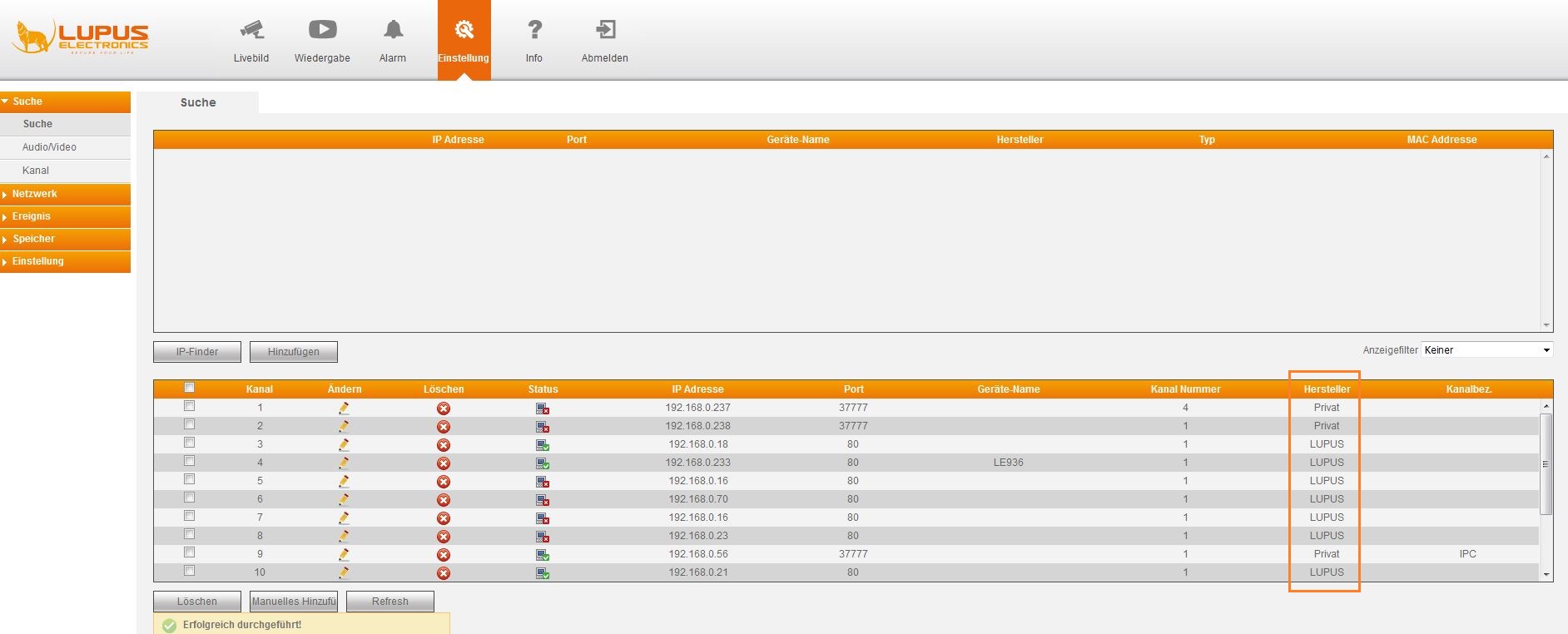
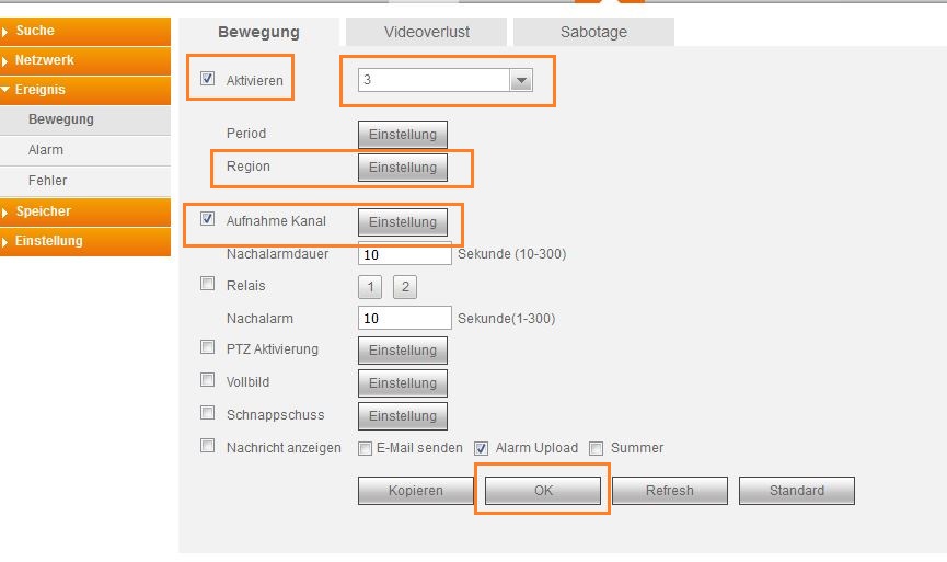
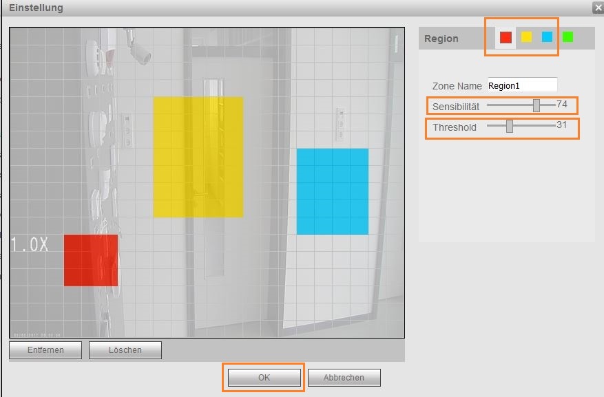
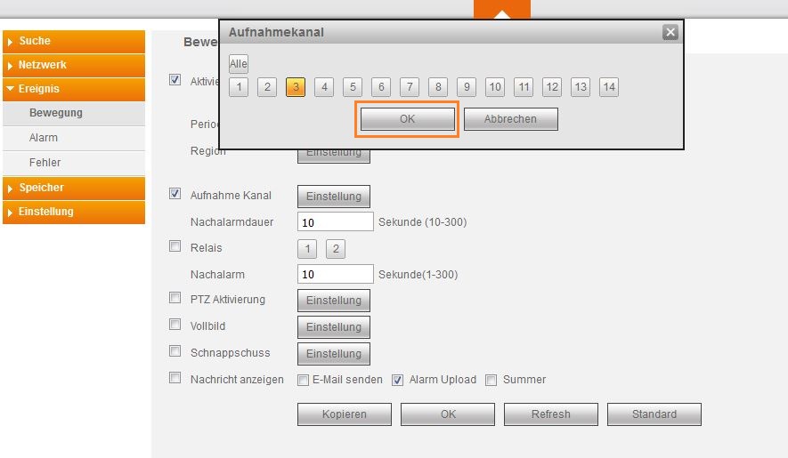
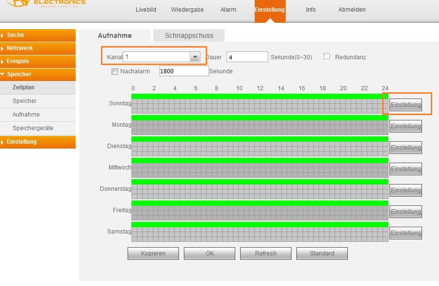
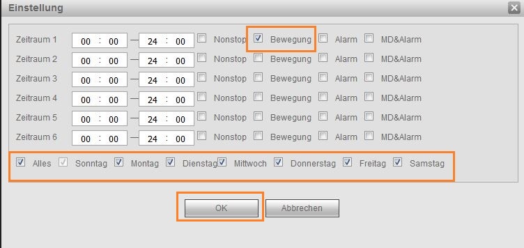
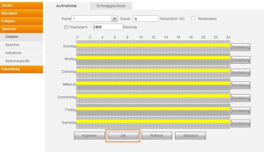
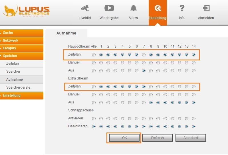
- Überprüfen Sie bitte zuerst ob auf Ihrer Kamera eine ältere Firmware installiert ist. Bei älteren Firmware Versionen ist es notwendig ein Firmware Update durchzuführen:
-
NVR (LE 914, LE 918, LE 926, LE928) - The motion detection of my NVR does not work with my LUPUSNET HD cameras.
-
Is it possible to get a single JPG image from the recorder?
-
Yes, please use the following syntax:
Devices LE2xx V1 & V2 generation)
- https://username:password@IP-address/cgi-bin/snapshot.cgi?channel=1
Example with a standardised IP address, username and passwort:
- https://admin:admin@192.168.123.101/cgi-bin/snapshot.cgi?channel=1
Devices LE2xx V3 generation)
- https://username:password@IP-address/cgi-bin/snapshot.cgi?channel=1
Example with a standardised IP address, username and passwort:
- https://admin:admin@192.168.123.101/cgi-bin/snapshot.cgi?channel=1
Recorder HDTV
-
How do I display the stream of my LE8xx V2 recorder in my XT alarm panel?
-
Use the following command in the XT:
http://Benutzername:Passwort@IP-Adresse/cgi-bin/mjpg/video.cgi?channel=channelNr&subtype=1
"Channel" allows you to choose the camera. Please use the channel number of the camera -1Set the frame itnervall of the second stream to 1sec in the recorder
-
How do I set up the motion detection on my DVR?
-
Bewegungserkennung richtig Einstellen (HDTV Rekorder)
Um die Bewegungserkennung der über einen Rekorder richtig einzurichten sind mehrere Schritte notwendig.
- Im Menü "Einstellung" → "Ereignisse" → "Erkennung" → "Bewegung" müssen Sie nun die Kamera auswählen welche die Bewegungserkennung auslösen soll. Verwenden Sie dafür das Auswahlmenü neben dem Feld "Aktivieren".
- Neben dem Punkt "Region" finden sie den Knopf "Einstellung". In dem neuen Fenster sehen Sie einen Schnappschuss des Livebilds der gewählten Kamera.
Sie können nun Bewegungsbereiche vergeben indem Sie bei Region eine Farbe auswählen und mit dieser Felder im Bild markieren. Sie können bis zu drei verschiedene Regionen markieren.
Die Regler für "Sensibilität" und "Grenzwert" erlauben Ihnen festzulegen wie stark eine Bewegung sein muss.
Je höher die "Sensibilität" desto mehr Aufnahmen gibt es.
Je höher der "Grenzwert" desto weniger Aufnahmen gibt es.
Bestätigen Sie die Einstellungen mit "OK" - Neben "Aufnahme Kanal" können Sie nun wählen welche Kamera eine Aufnahme starten soll, wenn die oben eingestellte Kamera eine Bewegung erkennt. Normalerweise wird hier dieselbe Kamera gewählt welche auch die Bewegungserkennung auslöst.
Bestätigen Sie die Wahl des Aufnahme Kanals mit "OK". - Bestätigen Sie Ihre gesamten Einstellungen mit "OK"
- Gehen Sie nun in das Menü "Einstellung" → "Speicher" → "Zeitplan". In diesem Menü definieren Sie ob die Kamera eine Daueraufnahme macht oder auf Bewegungen reagiert.
- Hier können Sie wieder neben Kanal die Kamera wählen für welche Sie einen Zeitplan festlegen möchten.
- Klicken Sie bei einem der Wochentage auf "Einstellung" und das folgende Menü wird erscheinen:
- Um die Bewegungserkennung an allen Tagen zu aktivieren, setzen Sie bitte den Haken bei "Alles" und nur bei "Bewegung". Haken bei "Nonstop", "Alarm" und "MD&Alarm" entfernen Sie bitte.
- Bestätigen Sie Ihre Einstellungen mit "OK".
- Nun werden Ihnen an allen Tagen eine gelbe Markierung (Bewegungserkennung) angezeigt. Bestätigen Sie dies bitte mit "OK".
- Gehen Sie nun in das Menü "Einstellung" → "Speicher" → "Aufnahme" und stellen Sie Ihre Kameras auf Zeitplan. Erst jetzt wird die Kamera sich an den eingestellten Zeitplan halten.
- Nach Abschluss des letzten Schrittes wird die Kamera ab sofort mittels Bewegungserkennung aufnahmen auslösen.
-
Is it possible to display the MJPEG stream of the HDTV recorder in the alarm panel?
-
Yes, please use the following syntax:
- http://username:password@IP-address/cgi-bin/mjpg/video.cgi?channel=channelNo&subtype=1
Example with a standardised IP address, username and passwort:
- http://admin:admin@192.168.123.101/cgi-bin/mjpg/video.cgi?channel=1&subtype=1
Please note that this requires the latest firmware of the recorder and that your need to set the compression of the extra stream in the recorder to MJPEG.
-
LE 260HD / LE 261HD - Please do not change the HD protocol in the camera
-
Please do not change the video protocol / video output in the OSD menu of the camera. IF you change the protocol from the standard HD protocol, you cannot control the camera correctly anymore. In case you select TVI or AHD, a PTZ Keyboard with RS485 connection is required to change this option again.
-
Why is my camera not working when I use a long video system cable?
-
There is always a power loss when using an extension cord. The longer the extension, the higher is the power loss.
Please make sure to use a stronger mains adapter to counter this power loss.
-
Is it possible to get a single JPG image from the recorder?
-
Yes, please use the following syntax:
- http://username:password@IP-address/cgi-bin/snapshot.cgi?channel=channelNo
Example with a standardised IP address, username and passwort:
- http://admin:admin@192.168.123.101/cgi-bin/snapshot.cgi?channel=1
Recorder EOL Products
-
HD-SDI - LE 121 - Starkes Bildrauschen bei Dunkelheit, was tun?
-
Die Kamera ist standardmäßig auf 1080p mit 60 Bildern die Sekunde eingestellt. Die meißten Rekorder zeichnen jedoch nur 30 auf und stellen auch nur 30 Live dar. Bitte stellen Sie im Kamera OSD die FPS Zahl auf 25 oder 30 um (unter DISPLAY).
-
D1 models - Sobald Daten wiedergegeben werden, startet der Rekorder neu oder bleibt hängen.
-
Installieren Sie die neuste Firmware. Sollte dies nicht helfen, ist die interne Festplatte defekt und muss ausgetauscht werden.
-
Non HD models - The image is black and white and flickers
-
The recorder is set to NTSC.
The "+" series has a switch on the back to toggle between PAL and NTSC - please switch it to PAL.
The "D1" series has an auto recognition at startup - please connect the cameras to the recorder before you boot it.
LUPUS-Cloud: LUPUSCloud:
LUPUSCloud: General functions
-
Supported products
-
Unterschied Firmen- und Privatkonto
-
Unterschied Firmen- und Privatkonto
In einem Firmenkonto werden Gebäude automatisch in einer Firmenstruktur angelegt. Dabei werden die einzelnen Gebäude nach Land und Stadt geordnet. Ein Firmenkonto erlaubt zusätzlich Berechtigungen für alle Gebäude in der Firma auf einmal festzulegen (z.B. wenn Angestellte immer Zugriff auf alle Gebäue haben sollen, kann man diese auf einmal zu allen Gebäuden der Firma einladen). Natürlich kann man auch individuelle Berechtigungen für jedes einzelne Gebäude vergeben
Ein Privatkonto zeigt alle Gebäude gleichzeitig an. Es gibt keine Sortierung nach Land oder Stadt. Berechtigungen können nur individuell für jedes Gebäude einzeln vergeben werden.
Privatkonten sind für jeden der nur ein Gebäude hat übersichtlicher und schneller. Ebenfalls sind Privatkonten für Angestellte von Firmen gedacht (diese werden dann zu einem Firmenkonto über die Berechtigungen eingeladen).
-
Kachelansicht - Einstellungsmenü
-
Kachelansicht - Einstellungsmenü
Das Einstellungsmenü (Zahnrad) ist über die Kachelansicht bei jeder Firma, jedem Gebäude, Stockwerk, Wohnung und Raum verfügbar. Je nachdem auf welcher Ebene man Einstellungen vornimmt, gelten diese auch für alle unterliegenden Strukturen. D.h. eine Änderung auf Firmenebene gilt für alle Objekte/Räume dieses Firmenkontos; eine Änderung auf Stockwerkebene für alle Wohnungen/Räume des Stockwerks; eine Änderung auf Raumebene nur für diesen Raum.
Je nachdem auf welcher Ebene man auf das Einstellungsmenü zugreift, hat man unterschiedliche Optionen.
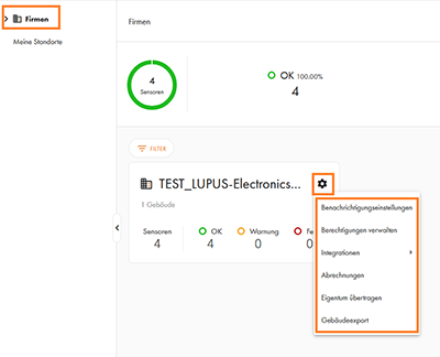
- Gebäudeebene:
- Gebäude
- Standort bearbeiten
- Duplikat
- Löschen
- Struktur exportieren
- Eigentum übertragen
- Nach: Privatgebäude // Nach: Firmengebäude
- Benachrichtigungseinstellungen
- Wartungsprotokolle
- Verbrauchsinformationen
- Mieterinformationen importieren
- Betriebskostenabrechnungen
- Berechtigungen verwalten
- Integrationen
- Sireneneinstellungen
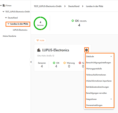
- Stockwerk
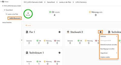
- Wohnung
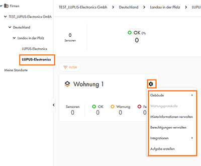
- Raum
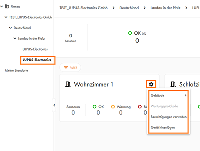
-
Listenansicht
-
Listenansicht
Über die Ansicht als Liste sehen Sie alle Rauchmelder der aktuell ausgewählten Strukturebene tabellarisch aufgelistet.
In der Listenansicht haben Sie Zugriff auf die Funktionen Filter, Suchen und exportieren. Ab der Gebäudeebene haben Sie zusätzlich die Option Auswählen (Aufgaben erstellen / Ticketsystem).
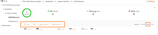
-
Schnellübersicht
-
Schnellübersicht
In dieser Übersicht sehen Sie die Gesamtanzahl der Melder auf der ausgewählten Strukturebene. Ebenfalls sehen Sie eine Aufschlüsselung nach Meldern ohne Probleme, mit Warnungen und Fehlern.
Über klicken auf die Melderanzahl bei "OK", "Warnung" oder "Fehler" wechseln Sie in die Listenansicht mit der ensprechenden Filterauswahl (z.B. alle Melder mit "Warnungen").
-
Integrationen in Wachzentralen, Gruppenalarmierungssystemen und Drittplattformen
-
Integrationen
Die Daten aus der Webplattform können Sie auch ganz einfach an andere Systeme weitergeben. Für Alarmmeldungen kann z.B. eine Wachzentrale via SIA DC 09 aufgeschaltet werden. Ebenfalls gibt es eine Webhook-Schnittstelle, mit welcher Sie Mitteilungen an ein System Ihrer Wahl übermitteln können. Der Vorteil der Aufschaltung bei einem Wachdienst liegt dabei, dass in einem Alarmfall eine jederzeit besetzte Stelle kontaktiert wird. Dies bedeutet, dass auch wenn Sie nicht erreichbar sind, Ihr Gebäude weiterhin geschützt ist.
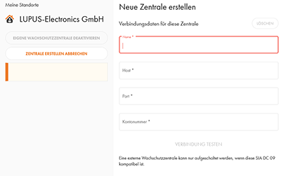
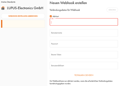
Speziell für die Feuerwehr und die Rauchfrüherkennung im Feuerwehrfahrzeug haben wir für unsere Mobilfunkrauchmelder die Möglichkeit bereitgestellt, diese auf viele der Gruppenalarmierungssysteme (Alamos, Alarm Dispatcher, Divera24/7, FeuerSoftware, Groupalarm, FF-Agent) aufzuschalten:
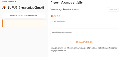
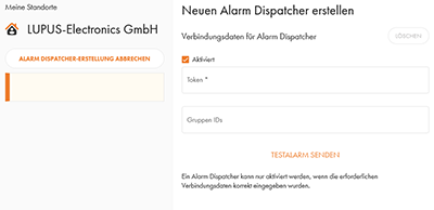
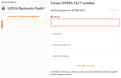
Groupalarm, FeuerSoftware und FF-Agent wird mittels der Webhooks verbunden:
-
Suchen & Filtern
-
Suche und Filter
In der Listenansicht der Geräte haben Sie die Möglichkeit über Filter nur bestimmte Arten von Meldern oder nur Melder mit bestimmten Meldungen angezeigt zu bekommen:
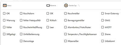
Über die Lupe erhalten Sie ein Suchfenster in welches Sie nach einem Melder anhand der Melder ID (vollständige ID oder nur ein Teil davon), sowie nach Namen der Gebäudestruktur suchen können.
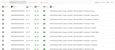
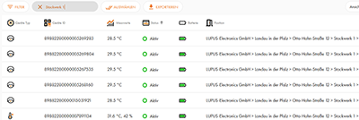
-
Aufgaben erstellen / Ticketsystem
-
Aufgaben erstellen / Ticketsystem
Die LUPUS-Cloud hat ein Ticketsystem integriert, mit welchem Sie an berechtige Personen Aufgaben verteilen können. Aufgaben können für komplette Stockwerke und einzelne Melder erstellt werden.
Um für ein Stockwerk eine Aufgabe zu erstellen, müssen Sie auf einem Stockwerk auf das Zahnrad → "Aufgabe erstellen" drücken
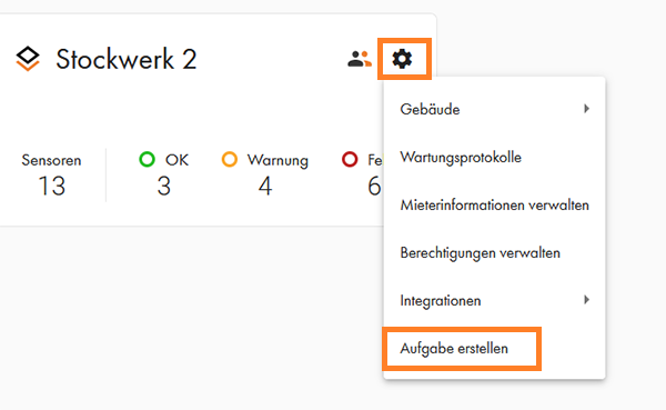
Um für einzelne Melder eine Aufgabe zu erstellen, müssen Sie in der Listenansicht auf "Auswählen" klicken, die entsprechenden Melder mittels der Checkbox auswählen und danach auf "Senden" klicken.
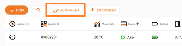
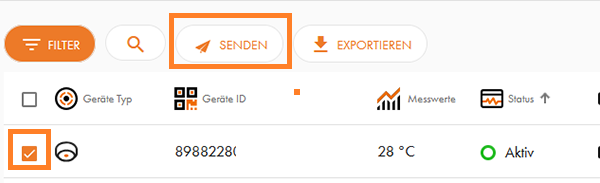
Bei der Erstellung von Aufgaben haben Sie im linken Bereich als erstes die Wahl an welche Person (via eingeladener E-Mailadresse) Sie die Aufgabe vergeben möchten. Danach können Sie zwischen drei vordefinierten Aufgaben. Ebenfalls gibt es ein Freitextfeld in welchem Sie Informationen zur Aufgabe hinterlegen können.
Über die Auswahl bei "Termin" und "Zeitraum" können Sie auch festlegen, wann die Aufgabe zu erledigen ist.Die Option "Geräte stummschalten" sorgt dafür, dass Sie von diesem Gerät keine Fehlermeldungen mehr über die Bedienoberfläche und die verschiedenen Übermittelungswege erhalten. Die Funktion des Geräts vor Ort wird durch diese Funktion nicht eingeschränkt.
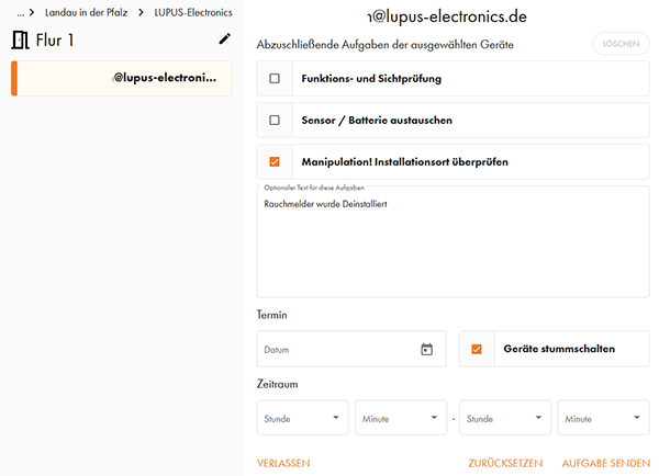
Nach Erteilung einer Aufgabe erhält die entsprechende Person eine E-Mail sowie eine Aufforderung die Aufagbe in der Bedienoberfläche anzunehmen.
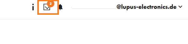
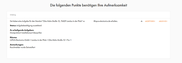
Ebenfalls wird der Statuskreis des entsprechenden Melders schwarz und zeigt an, dass für diesen Melder eine Aufgabe vorliegt. In der Listenansicht haben berechtigte Personen auch Zugriff auf die Aufgabenverwaltung.
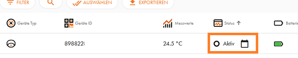
Nach Abschluss der Aufgabe, wird die Aufgabe entsprechend abgeschlossen.
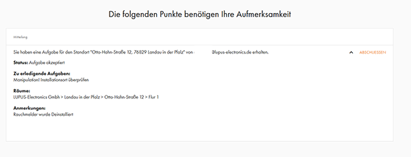
LUPUSCloud: Building settings
-
Standort bearbeiten
-
Standort bearbeiten
Über diese Schaltfläche haben Sie die Möglichkeit sowohl Name und Adresse zu ändern. Ebenfalls können Sie die Gebäudestruktur ändern und Stockwerke, Wohnungen, Räume, usw. hinufügen, löschen und umbenennen.
-
Berechtigungen verwalten
-
Berechtigungen verwalten
Auf jeder Verwaltungsebene (Firma, Gebäude, Stockwerk, Wohnung, Raum) können Sie über die Schaltfläche "Berechtigungen verwalten" weitere Nutzer einladen. Diese Nutzer sehen dann alle Rauchmelder der Strukturebene zu dieser sie eingeladen worden. Ein Nutzer, der auf der Ebene Firma eingeladen wird, sieht alle Melder in allen Gebäuden dieser Firma. Ein Nutzer, der auf der Gebäudeebene eingeladen wird, sieht alle Melder in diesem Gebäude, usw..
Wenn Sie neue Nutzer einladen, haben Sie die Wahl zwischen verschiedenen voreingestellten Berechtigungen (Admin, Installateur, lokaler Benutzer). Über Benutzerdefiniert können Sie aber auch komplett eigene Berechtigungen vergeben:
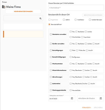
- Standorte verwalten
- Neu – Berechtigung neue Gebäude zu erstellen
- Bearbeiten – Berechtigung die Struktur bestehender Gebäude zu ändern
- Löschen – Berechtigung bestehende Gebäude zu löschen
- Scharfschalten – Berechtigung Alarmfunktionen zu aktivieren/deaktivieren (z.B. für Alarmmeldungen des Mobilfunk Bewegungsmelder)
- Importieren – Berechtigung Gebäudestrukturen per Importfunktion hinzuzufügen
- Geräte verwalten
- Neu – Berechtigung neue Melder hinzuzufügen
- Bearbeiten – Berechtigung Einstellungen bestehender Melder zu bearbeiten (z.B. Temperaturbereiche bei Temperatursensoren oder Einstellungen eines SWAN-Gateways) und Warnmeldungen (z.B. Demontage) zu bestätigen.
- Löschen – Berechtigung Melder stillzulegen
- Ansicht – Berechtigung Melder und Melderdetails zu sehen
- Berechtigungen
- Teilen – Berechtigung weitere Nutzer einzuladen
- Widerrufen – Berechtigung Nutzer zu entfernen
- Ansicht – Berechtigung zu sehen, welche Nutzer ebenfalls Zugriff haben
- Benachrichtigungen
- Konfigurieren – Berechtigung einzustellen, welche Meldungen man von der LUPUS-Cloud erhalten möchte (per E-Mail, Push-Nachricht und Webplattform)
- Wachzentralen
- Neu – Berechtigung neue Wachzentralen aufzuschalten
- Bearbeiten – Berechtigung die (Verbindungs)details zu bestehenden Wachzentralen zu bearbeiten
- Löschen – Berechtigung eine aufgeschaltete Wachzentrale zu entfernen
- Ansicht – Berechtigung zu sehen, welche Wachzentralen aufgeschaltet sind
- Mieterinformationen
- Neu/Bearbeiten – Berechtigung in Wohnungen Mieterinformationen zu hinterlegen und zu editieren
- Löschen – Berechtigung hinterlegte Mieterinformationen zu löschen
- Ansicht – Berechtigung in Wohnungen hinterlegte Mieterinformationen zu sehen
- Abrechnungen
- Neu/Bearbeiten – Berechtigung neue Betriebskostenabrechnungen zu erstellen, bzw. Werte anzupassen
- Löschen – Berechtigung erstelle Betriebskostenabrechnungen zu löschen
- Ansicht – Berechtigung erstellte Betriebskostenabrechnungen einzusehen
- Automation
- Neu/Bearbeiten/Löschen – Berechtigung Zeitpläne für die automatische scharf-/unscharfschaltung von Mobilfunk Bewegungsmeldern zu hinterlegen
- Ansicht – Berechtigung hinterlegte Zeitpläne zu scharf-/unscharfschaltung von Mobilfunk Bewegungsmeldern zu sehen
- Wartungsprotokolle
- Herunterladen – Berechtigung Wartungsprotokolle zu erstellen und herunterzuladen
- Anfangsdatum der Erlaubnis
- Ab diesem Zeitpunkt wird die Person eingeladen und hat den gewährten Zugriff
- Ablaufdatum der Erlaubnis
- Bis zu diesem Zeitpunkt hat die Person zugriff. Nach Ablauf dieses Datums werden die gewährten Rechte automatisch entzogen. Wird dieses Feld leergelassen, gibt es keine zeitliche Beschränkung der Einladung.
-
Benachrichtigungsfilter
-
Benachrichtigungseinstellungen
Jedes Objekt ist anders und jede Person hat andere Präferenzen bei Benachrichtigungen. Daher haben Sie in der Plattform die Wahl, welche Benachrichtigungen Sie auf welchem Weg erhalten möchten. Sie können frei definieren, welche Meldungen Sie per E-Mail, Push-Nachricht oder auf der Webplattform erhalten. Damit stellen Sie sicher, dass Sie immer die Nachrichten bekommen, die wirklich für Sie wichtig sind:
Benachrichtigungen per E-Mail.
Diese Optionen können Sie für jede E-Mailadresse individuell für die Ebenen Firma, Gebäude oder Wohnung einstellen.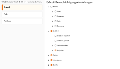
Benachrichtigungen per Push-Nachricht:
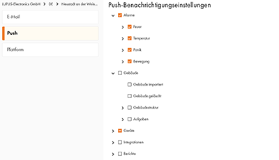
Benachrichtigungen auf der Webplattform:
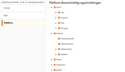
-
Eigentum übertragen
-
Eigentum übertragen
Eigentum übertragen erlaubt es Firmen und Gebäude an einen anderen Besitzer zu übergeben. Laden Sie den neuen Eigentümer per E-Mailadresse ein. Dieser erhält eine Aufforderung die Eigentumsübertragung zu akzeptieren. Danach werden die eigenen Berechtigungen gelöscht und man kann das Objekt nicht mehr sehen und hat keinerlei Zugriff mehr.
-
Nach: Privatgebäude / Nach: Firmengebäude
-
Nach: Privatgebäude / Nach: Firmengebäude
Mittels dieser Schaltfläche können Sie ein Gebäude in die jeweils andere Struktur übertragen. Ein Firmengebäude wird zu einem Privatgebäude und danach unter "Meine Gebäude" angezeigt. Ein Privatgebäude wird zu einem Firmengebäude und entsprechend in der Firmenstruktur integriert.
Dies ist natürlich nur möglich, wenn Sie ein Firmenkonto erstellt haben.
Über diese Schaltfläche können Sie Privatgebäude nur Ihrer eigenen Firma hinzufügen. Zu Firmen in die Sie eingeladen wurden, können Sie über diese Schaltfläche keine Gebäude zuordnen. Sollte dies notwendig sein, übertragen Sie das Eigentum an diesem Gebäude erst an den Firmeninhaber – dieser kann danach das Gebäude in die Firmenstruktur aufnehmen.
-
Duplikat
-
Duplikat
Diese Schaltfläche erlaubt es Ihnen die aktuelle Struktur inklusive aller Unterebenen zu kopieren.
Die neue Struktur wird mit einem "- 1" als Kopie gekennzeichnet und kann danach umbenannt werden (via "Gebäude" → "Standort bearbeiten"). Die Namen aller Unterebenen erhalten keine Änderungen. Melder die in einer original Struktur enthalten sind, werden nicht koppiert (weder aktive noch stillgelegte).
-
Löschen
-
Löschen
Mit dieser Schaltfläche löschen Sie die entsprechende Struktur und alle Unterebenen. Löschen Sie z.B. eine Wohnung, werden auch alle Räume in der Wohnung gelöscht – Löschen Sie ein Haus, werden alle Stockwerke, Wohnungen, Räume in diesem Haus ebenfalsl gelöscht.
Löschen ist nur möglich, wenn sich in dieser Sturktur und allen zugehröigen Unterebenen keine aktiven Melder befinden. Wenn Sie eine Struktur löschen möchten, in der es noch aktive Melder gibt, müssen Sie diese erst mittels der Schaltfläche "Gerät außer Betrieb nehmen" in der Detailansicht des Melders stilllegen.
-
Gebäudeexport
-
Gebäudeexport
Diese Funktion auf der Firmenebene erlaubt es Ihnen eine Exportdatei aller Gebäude der Firma inkl. der in den Gebäude zugeordneten Rauchwarnmelder zu erstellen.
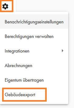
LUPUSCloud: Device functions
-
Rüttelkissen an Mobilfunksirene anschließen
-
Rüttelkissen für Mobilfunkrauchmelder / Mobilfunksirene
Wir haben das Rüttelkissen EI174 getestet - der Anschluss jedes anderen Rüttelkissens welcher über ein Relais per 12V oder potentialfrei ausgelöst werden kann, ist aber ebenfalls möglich.
Um es anzuschließen, muss man den Stecker des EI174 abschneiden – danach ist es mit unserer Sirene zusammen komplett funktionsfähig.Nach auslösen eines Alarms wird der Alarmausgang der Mobilfunksirene geschaltet und das Kissen löst aus.
Für den Anschluss muss man das Kabel des Kissens (EI174 – benötigt 12V) sowohl mit der Stromversorgung und dem Alarmausgang der Sirene verbinden (rotes und schwarzes Kabel von unten kommend im Bild). Zusätzlich muss die Stromversorgung der Sirene mit dem COM der Sirene gebrückt werden (weißes Kabel das die beiden Klemmleisten brückt).
-
Wie erkennt der Rauchmelder Hindernisse und wie schnell kann dies gemeldet werden?
-
Wie erkennt der Rauchmelder Hindernisse und wie schnell kann dies gemeldet werden?
Bei der Erstinbetriebnahme führt der Rauchmelder eine Umfelderkennung durch. Dabei wird der aktuelle Zustand bei der Installations erfasst. Danach wird bei jeder Selbstinspektion (alle 24h) geprüft, ob sich etwas an diesem Zustand geändert hat.
Sollte sich etwas geändert haben, wird man darüber bei der Übermittelung der Inspektionsdaten informiert.Kritische Meldungen wie "Rauchalarm" oder "Demontage" werden immer sofort übermittelt!
Aus diesem Grund ist es wichtig, dass der Rauchmelder erst an seinem Installationsort in Betrieb genommen wird. Nimmt man den Rauchmelder an einem anderen Ort in Betrieb (z.B. auf dem Schreibtisch), führt dies dazu, dass sich der Rauchmelder nicht auf die korrekte Umgebung kalibiert hat. In diesem Fall muss man den Rauchmelder in den Lagermodus zurücksetzen und am Installationsort neu Inbetrieb nehmen.
-
Wie oft meldet der Rauchmelder ein Signal an die Cloud?
-
Wie oft meldet der Rauchwarnmelder an die Cloud?
Wie oft sich der Rauchmelder an der Cloud meldet, hängt vom Netzempfang und der Mitteilung ab. Kritische Meldungen wie "Rauchalarm" oder "Demontage" werden immer sofort übermittelt!
- Guter Empfang: Der Rauchmelder sendet täglich ein Signal mit den aktuellen Inspektionsdaten
- Mittlerer Empfang: Der Rauchmelder sendet alle 3-4 Tage ein Signal mit den gesammelten Inspektionsdaten.
- Schlechter Empfang: Der Rauchmelder sendet alle 7-10 Tage ein Signal mit den gesammelten Inspektionsdaten.
-
Exportieren
-
Exportieren
Die Schaltfläche "Exportieren" in der Listenansicht erlaubt es Ihnen die Geräte IDs aller Melder in der aktuellen Sturkturebene herunterzuladen. Die Datei die dabei erstellt wird, enthält ausschließlich die Geräte IDs. Es sind keinerlei Informationen oder Positionsbezeichnungen in der Datei enthalten. Die Datei selbst kann beim Download frei bennant werden. Standardmäßig erhält die Datei den Namen der Struktur die exportiert wurde (z.B. "Geräteliste-Firmenname-Land-Stadt-Gebäudename").
-
Wartungsprotokolle
-
Wartungsprotokolle
Wartungsprotokolle herunterladen
Das Menü Wartungsprotokolle erlaubt Ihnen manuell oder automatisiert die Wartungsprotokolle aller Rauchwarnmelder herunterzuladen. Je nachdem auf welcher Ebene Sie das Menü öffnen, erhalten Sie die Wartungsprotokolle eines einzelnen Rauchmelders, aller Rauchmelder in einem Raum, aller Rauchmelder einer Wohnung, aller Rauchmelder eines Stockwerks oder aller Rauchmelder eines Gebäudes.
Automatische Wartungsprotokolle
In diesem Menü können Sie festlegen, dass Sie automatisch die Wartungsprokolle an Ihre E-Mailadresse übermittelt bekommen. Sie haben die Wahl zwischen verschiedenen Arten der monatlichen sowie jährlichen Übermittelung. Wenn Sie bei der jährlichen Übermittelung ein individuelles Datum festlegen, erhalten Sie die Wartungsprotokolle immer am ausgewählten Tag.
Die Wartungsprotokolle werden Ihnen per E-Mail als XXX-Anhang übermittelt.
-
Geräte hinzufügen
-
Gerät hinzufügen
Mittels dieser Schaltfläche können Sie in der Webansicht einen Melder mittels manueller Eingabe der Melder ID (ICCID) hinzufügen. Der Melder muss dafür bereits in Betrieb sein und die "erfolgreich Verbunden" Melodie ausgegeben haben. Das manuelle hinzufügen auf diese Art ist immer nur eine gewisse Zeit nach der letzten Übermittelung eines Melders möglich
Standardmäßig sollten Melder immer mittels QR-Code scannen über die App hinzugefügt werden.
-
Sireneneinstellungen
-
Sireneneinstellungen
In diesem Menü legen Sie fest, welche Rauchmelder in einem Objekt alle zusätzlichen Sirenen in diesem Objekt (Mobilfunksirenen & Mobilfunk Alarm Buttons) auslösen sollen.
Es können nur zusätzliche Sirenen ausgelöst werden, die dem selben Gebäude zugeordnet sind.
Melder in einem Raum der angehakt ist, lösen alle zusätzlichen Sirenen in diesem Gebäude aus.Haben Sie einen Gebäudekomplex welcher aus zwei oder mehr Häusern besteht, die bei einem Rauchalarm alle alarmiert werden sollen, so erstellen Sie dafür nur ein Gebäude und erstellen die Unterteilung in einzelne Häuser durch die Stockwerkebene. Dies ist ein Spezialfall, da bei komplett getrennten Wohnhäusern ein häuserübergreifender Alarm meist nicht gewünscht ist. In Gewerbeimmobilien kann dies anders sein.
-
Gerät außer Betrieb nehmen
-
Gerät außer Betrieb nehmen
Mittels dieser Schaltfläche in der Detailansicht jedes Melders können Sie einen Melder stilllegen. Dies sorgt allerdings nur dafür, dass die Bedienoberfläche alle ankommenden Signale eines Melders ignorieren wird. Dadurch werden Sie keinerlei Signale oder Alarme eines Melders mehr erhalten. Die lokale Funktion eines Melders (z.B. Rauchwarnmelders) wird hier durch nicht beeinflusst – auch ein in der Bedienoberfläche außer Betrieb genommener Melder wird weiterhin lokal Alarme auslösen.
Diese Funktion muss genutzt werden, wenn man z.B. einen Melder einem anderen Raum zuordnen oder einen Raum löschen möchte. Ebenfalls muss diese Option als erster Schritt durchgeführt werden, wenn man einen Melder komplett außer Betrieb nehmen möchte (dafür muss in einem zweiten Schritt noch ein Reset direkt am Melder durchgeführt werden).
Geräte die auf diese Art außer Betrieb genommen wurden, werden weiterhin als "Stillgelegt" in der Oberfläche angezeigt. Dies ist notwendig, damit nachvollzogen werden kann, dass ein Raum mit einem funktionsfähigen Rauchwarnmeldern ausgerüstet war (z.B. nach einem Rauchwarnmeldertausch).
-
Lagermodus
-
Gerät in den Lagermodus zurücksetzen
Ein Rauchmelder welcher in der Oberfläche außer Betrieb genommen wurde, ist lokal immer noch komplett funktionsfähig. Um diesen komplett zu deaktivieren, müssen Sie den Rauchmelder noch in den Lagermodus zurücksetzen:
- Resettaster drücken und halten.
- Bedientasterdrücken drücken und halten.
- Resettaster loslassen.
- Es ertönen zwei kurze Töne.
- Bedientaster weiterhin gedrückt halten.
- Nach ein 15-20 Sekunden ertönt ein kurzer Ton, gefolgt von zwei weiteren Tönen.
- Es ist wichtig, dass auch die beiden kurzen Töne ausgegeben werden.
- Jetzt kann man den Bedientaster lösen, das Gerät befindet sich im Lagermodus.
-
Eichfrist hinterlegen
-
Eichfrist hinterlegen
Bei Zählern die einer Eichfrist unterliegen, können Sie in der LUPUS-Cloud ganz einfach entsprechende Erinnerungen hinterlegen. Gehen Sie dazu in die Detailansicht des jeweiligen Zählers und klicken Sie auf das Zahnrad
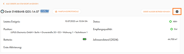
Im folgenden Menü können Sie das Eichjahr und die Eichzeit hinterlegen. Ebenfalls stellen Sie ein, wie viele Monate vor Ablauf der Eichzeit Sie benachrichtigt werden möchten. Die LUPUS-Cloud wird Melder, die die eingestellte Meldezeit erreichen, automatisch für Sie hervorheben. Zusätzlich haben Sie auch noch ein Textfeld für die Messlokation.
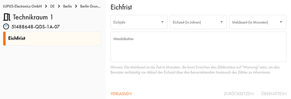
LUPUSCloud: OMS device management
-
SWAN OMS-Gateway einrichten
-
SWAN OMS-Gateway einrichten
Um einen SWAN OMS-Gateway in Betrieb zu nehmen, müssen Sie als erstes die Stromversorgung des Gateways herstellen und danach mit der LUPUS-Cloud App den QR-Code auf dem Gateway abscannen. Damit ordnen Sie den Gateway auch direkt einem Raum in Ihrem Gebäude zu.
Stellen Sie in den "Uploadeinstellungen" direkt ein, wie oft der Gateway Daten an die LUPUS-Cloud übermitteln soll. Für die ersten Einstellungen empfehlen wir stündlich oder täglich.
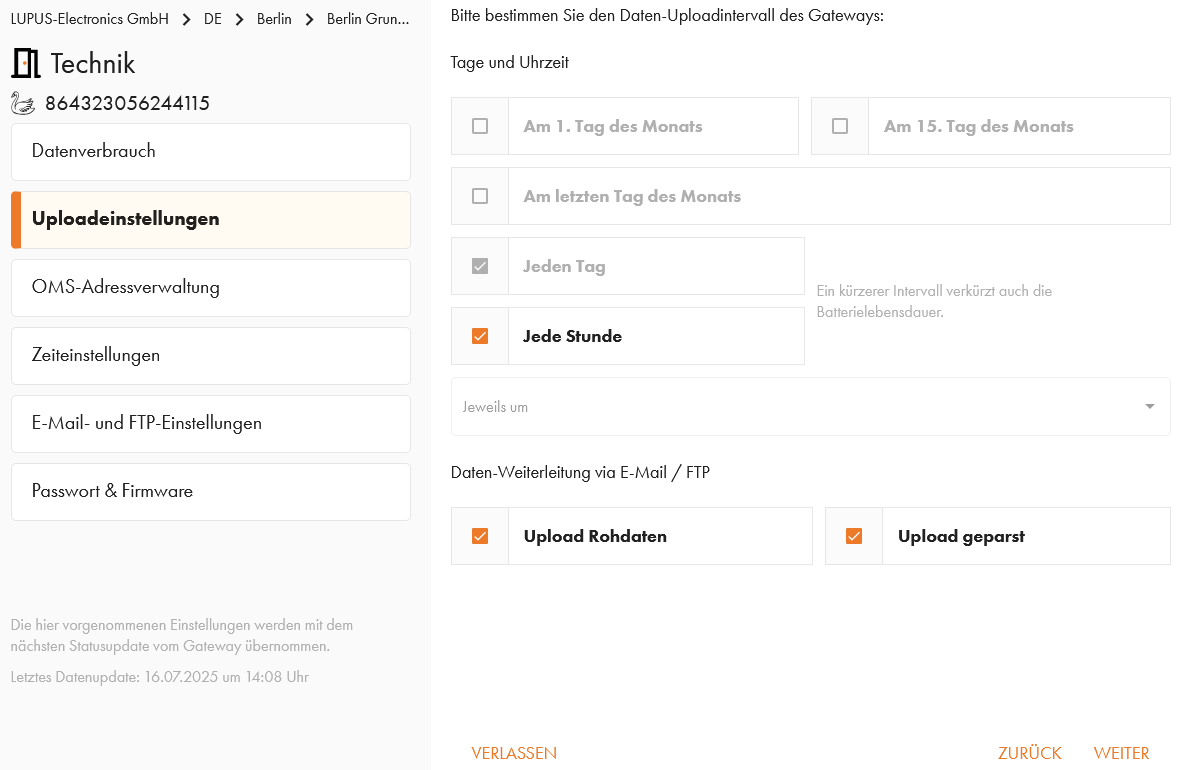
Nach der initialen Einrichtung sollte dies auf maximal zwei Mal pro Monat angepasst werden.
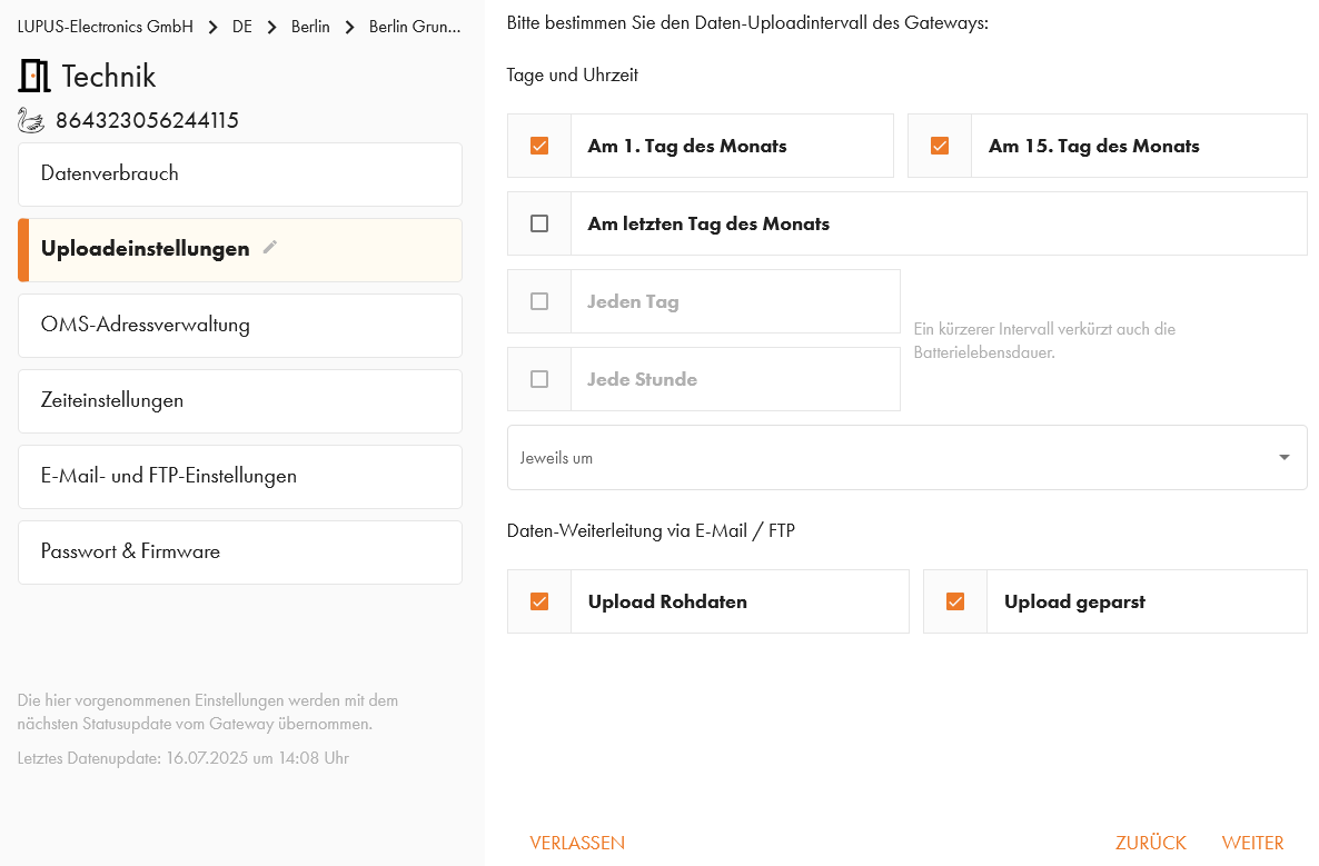
In der darauf folgenden "OMS-Adressverwaltung" erhalten Sie zwei Tabellen. In der oberen Tabelle sehen Sie alle OMS-Geräte die aktuell vom OMS-Gateway empfangen worden.
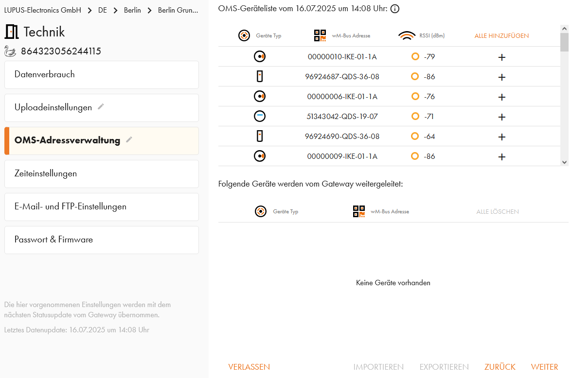
Die untere Tabelle ist eine Whitelist von allen OMS-Geräten, die vom OMS-Gateway an die LUPUS-Cloud übermittelt werden. Ist die Whitelist leer, werden immer die Daten aller Geräte übermittelt.
- Wir empfehlen alle OMS-Geräte, die übermittelt werden sollen in die Whitelist aufzunehmen. Dies stellt sicher, dass der OMS-Gateway keine Datenvolumen für OMS-Geräte verwenden muss, die nicht zu Ihrem Gebäude gehören.
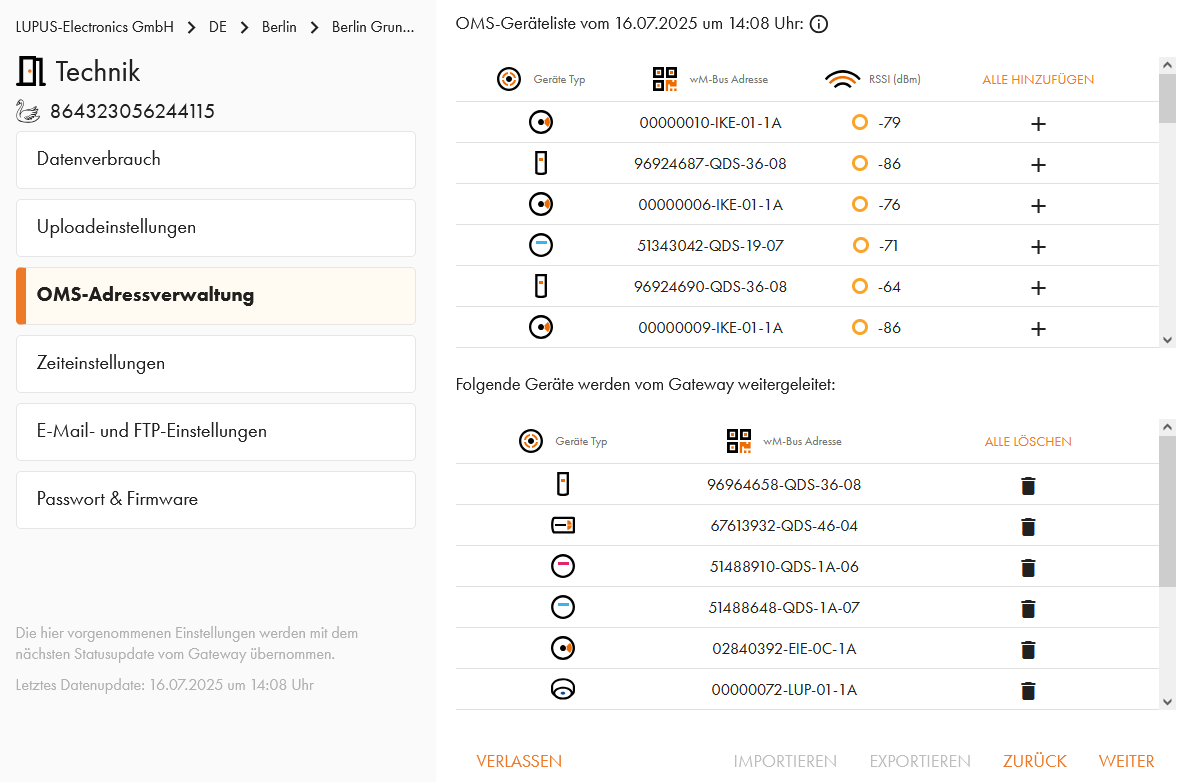
Für die automatische Weiterleitung der OMS-Daten können Sie im Menü "E-Mail- und FTP-Einstellungen" entsprechende Daten hinterlegen.
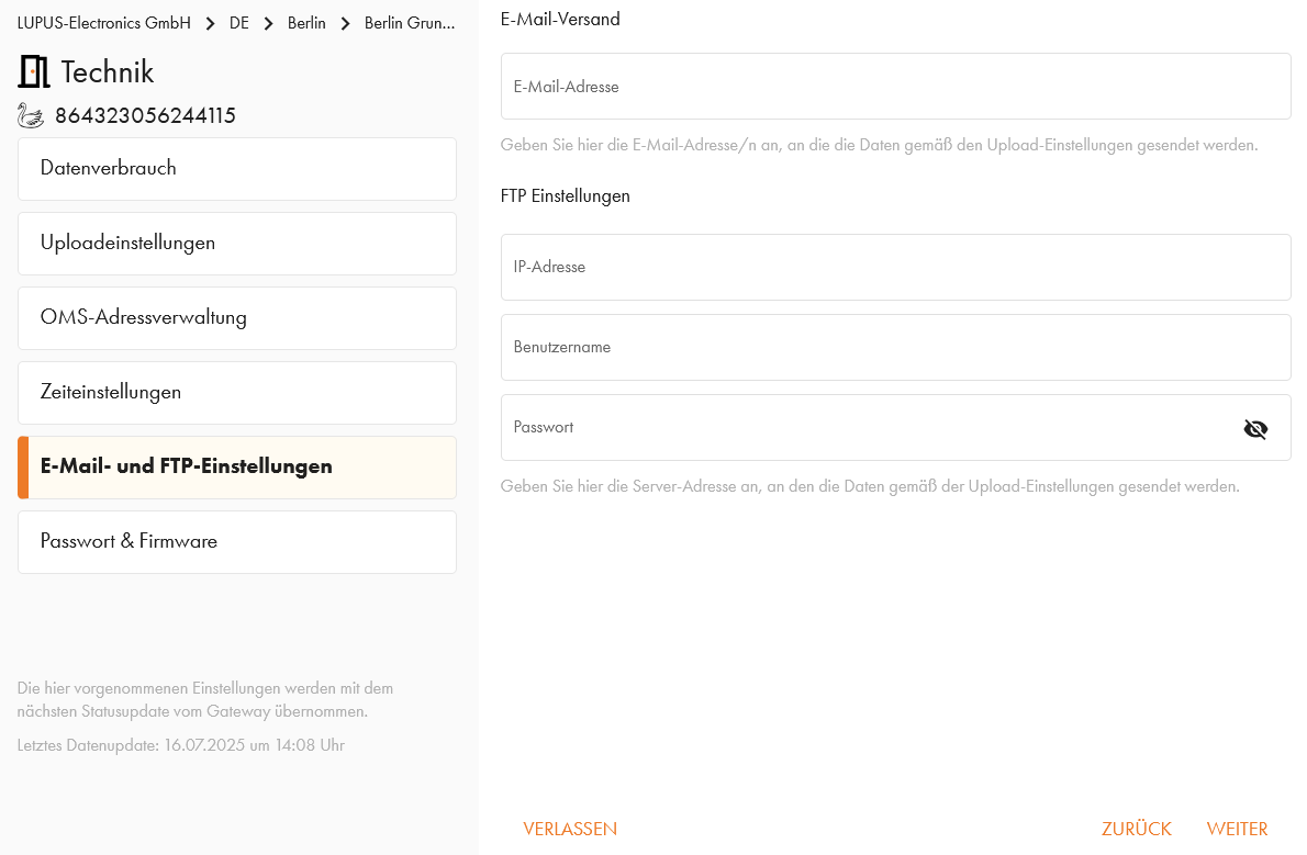
Ebenfalls muss direkt bei der Einrichtung ein neues Passwort für den OMS-Gateway hinterlegt werden.
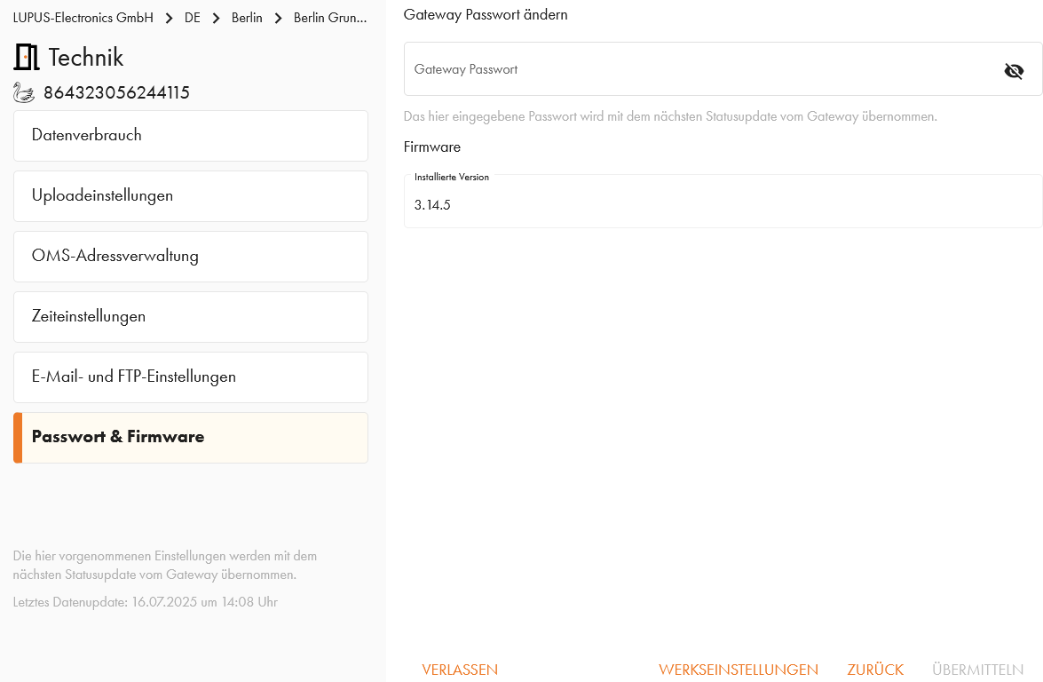
-
OMS-Geräte hinzufügen
-
OMS-Geräte hinzufügen
Nachdem Sie einen SWAN OMS-Gateway Ihrem Gebäude in der LUPUS-Cloud hinzugefügt haben, können Sie in jedem Raum OMS-Geräte hinzufügen.
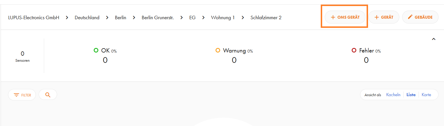
Hier erhalten Sie eine Auswahl aller OMS-Geräte die von Ihrem SWAN OMS-Gateway empfangen werden. Ist eine OMS-Whitelist festgelegt, werden nur diese OMS-Geräte angezeigt. Über das "+" Zeichen neben dem OMS-Gerät wird die ID in das "Geräte-ID" Feld übertragen und Sie können den zugehörigen AES Key eingeben (falls die Datenübertragung des OMS-Geräts verschlüsselt ist).
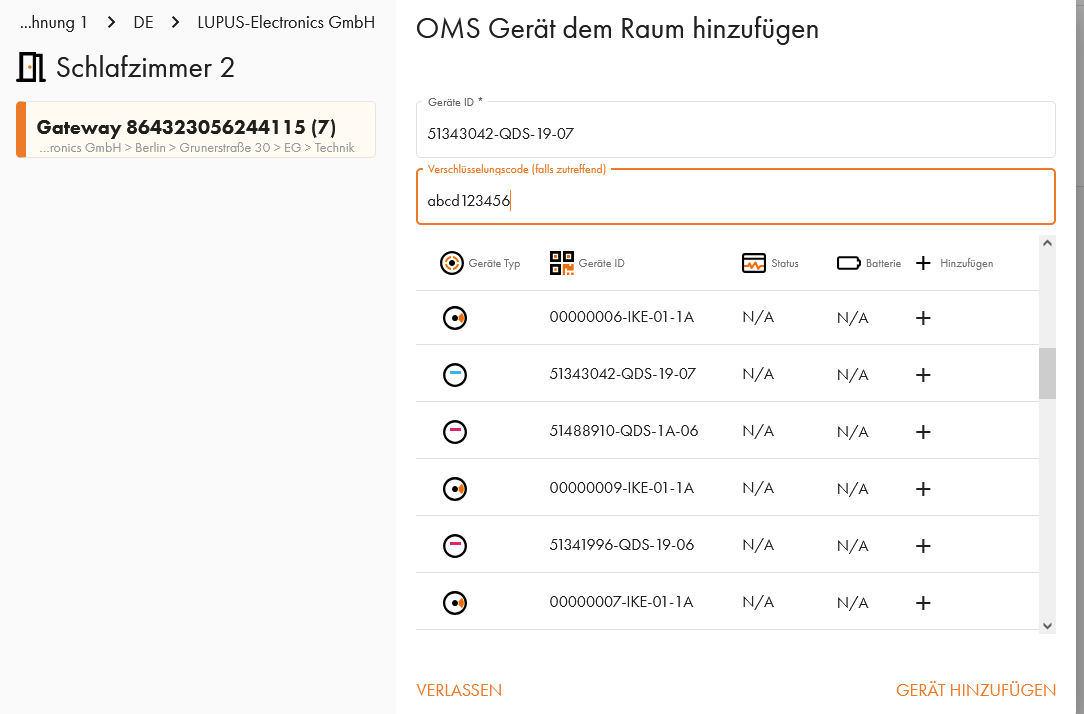
Danach wird Ihr OMS-Gerät mit entsprechenden Zählerständen in der LUPUS-Cloud angezeigt
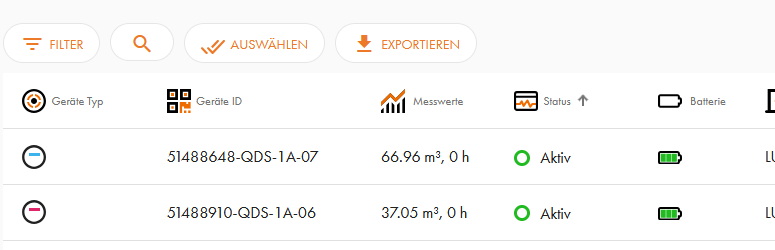
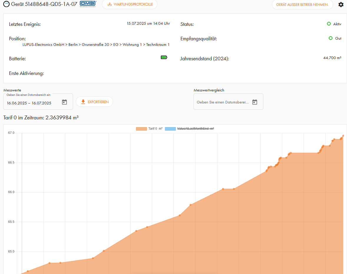
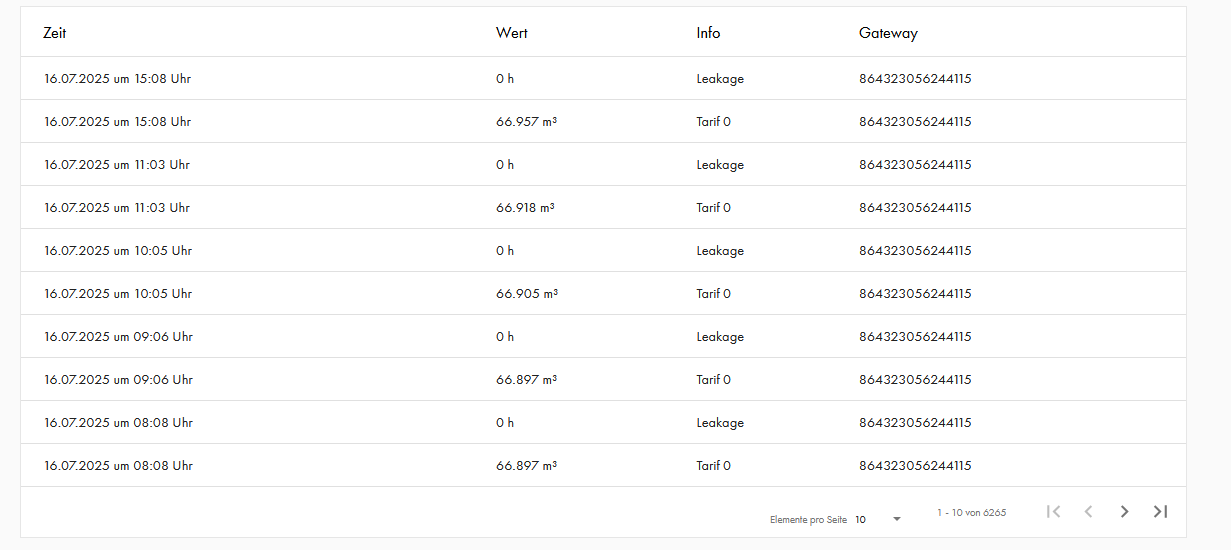
-
Unterjährige Verbauchsinformation (UVI)
-
Unterjährige Verbrauchsinformation (UVI)
Mit der LUPUS-Cloud und hinterlegten Mieterdaten, können Sie ganz einfach die UVI erfüllen. Der OMS-Gateway lädt automatisch die Verbrauchsdaten in die Onlineplattform und Ihre Mieter können jederzeit den Monatsverbrauch sehen und mit dem Verbrauch des Vormonats und den Verbrauch in einem frei definierbaren Zeitraum vergleichen. Sie selbst müssen nach der Einladung Ihrer Mieter zu der Plattform nichts mehr tun.
- Ansicht des Verbrauchs eines kompletten Gebäudes:
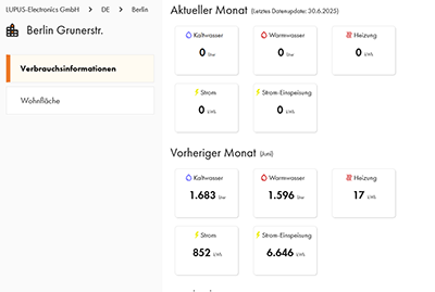
- Ansicht des Verbrauchs einer einzelnen Wohnung:
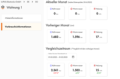
-
Abrechnungen
-
Abrechnungen
Über die Schaltfläche "Abrechnungen" auf der Firmenebene haben Sie Zugriff auf alle einmaligen und laufenden Kosten, die z.B. bei der Verwendung eines SWAN OMS Gateways oder der Erstellung von Betriebskostenabrechnungen anfallen
Im "Finanz Dashboard" erhalten Sie eine Übersicht über die Kosten im aktuellen Monat, im aktuellen Jahr und einem frei einstellbaren Zeitraum:

Im Menü "Abonnements" werden alle Geräte gelistet, für die laufende Kosten anfallen. Ebenfalls wird angezeigt wann die Geräte in Betrieb genommen wurden und bis wann diese aktiv sind.
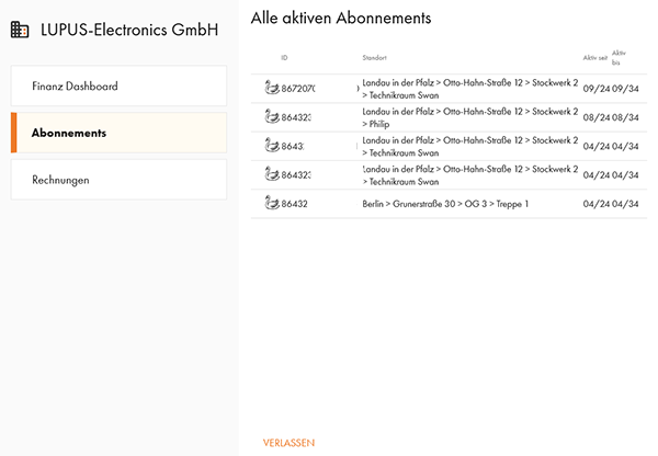
Im Menü "Rechnungen" werden Ihnen alle Rechnungen angezeigt. Sowohl mit Erstellungsdatum, Fälligkeitsdatum und Nettobetrag. In diesem Menü können Sie die Rechnungen auch über das Download Symbol herunterladen
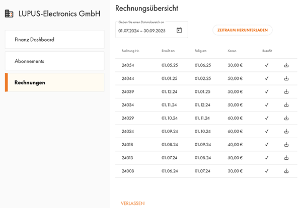
LUPUSCloud: UVI und Nebenkosten
-
Mieterverwaltung
-
Mieterverwaltung
Das Menü Mieterverwaltung ermöglicht Ihnen bei jeder Wohnung die Daten Ihrer Mieter zu hinterlegen. Dadurch können Sie in späteren Schritten für jeden Mieter eine Betriebskostenabrechnung erstellen. Ebenfalls erlaubt dies eine automatische unterjährige Verbrauchsinformation (UVI) an den Mieter sowie Alarmmeldungen der Mobilfunkrauchmelder direkt an den Mieter.
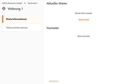
- Hinterlegen Sie die Daten des Mieters. Die Schaltfläche "Einladung senden" erlaubt Ihnen dem Mieter direkt eine Einladung zukommen zu lassen.
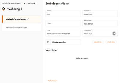
- Wenn ein Mieter auszieht, können Sie das Datum des Auszugs hinterlegen. Nach dem Auszug wird der Mieter in einer Liste der Vormieter aufgenommen (diese können auch gelöscht werden):
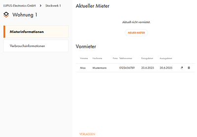
-
Import von Mieterdaten
-
Import von Mieterdaten
Die Importfunktion für Mieterdaten erlaubt es Ihnen Mieterdaten den jeweiligen Wohnungen zuzuordnen. Dabei handelt es sich um Vorname, Nachname, Telefonnummer und E-Mailadresse.
Den Mieterimport finden Sie über das Einstellungszahnrad auf der Gebäudeebene.
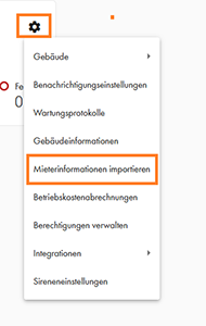
Wählen Sie im ersten Schritt die Exceldatei aus, in der die Mieterdateien hinterlegt sind. Achten Sie beim Einzugsdatum darauf, dass der Datentyp dieses Feldes als "Text" definiert ist.
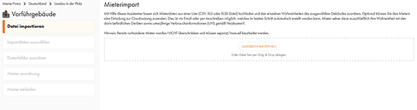
Nun wird Ihnen angezeigt, welche Kontaktdaten in der Datei enthalten sind. Hier können Sie anhaken, welche Daten Sie aus dieser Datei importieren möchten.
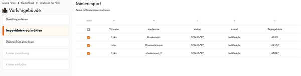
Im nächsten Schritt ordnen Sie zu, welche Spalte welche Informationen enthält, bzw. ob Sie die Informationen in dieser Spalte importieren möchten.
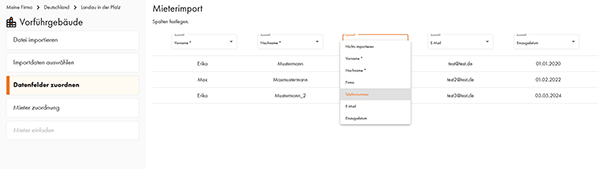
Im nächsten Menü legen Sie fest, welcher Mieter in welcher Wohnung wohnt. Achten Sie hier darauf, dass Sie Mietern nur Wohnungen zuweisen.
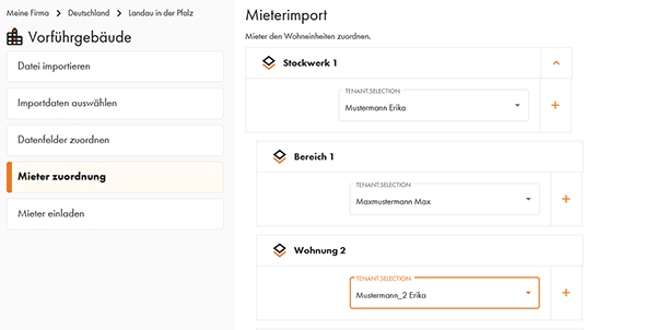
Im letzen Schritt können Sie den Mietern automatisch eine Einladung zu der jeweiligen Wohnung zukommen lassen. Möchten Sie keine automatische Einladungsemail an die Mieter versenden, entfernen Sie den Haken bei "Einladung senden".
Alternativ können Sie über "Einladungs-pdf" auch eine pdf Datei für den späteren Postversand herunterladen.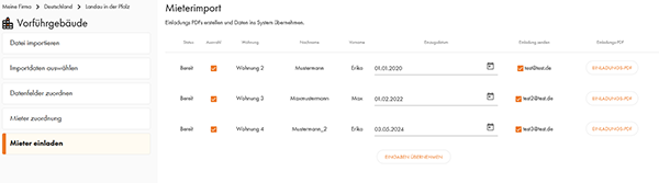
-
Mietereinladung
-
Mietereinladungen
Nachdem Sie einen Mieter in einer Wohnung hinterlegt haben, können Sie dem Mieter eine Einladung zukommen lassen:
- Wenn Sie die E-Mailadresse des Mieters haben, erhält der Mieter eine entsprechende E-Mail.
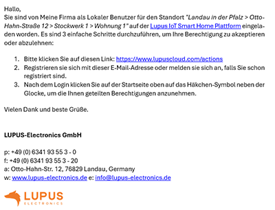
- Ansonsten können Sie ein pdf für den Briefversand erstellen.
-
Betriebskostenabrechnung
-
Betriebskostenabrechnung
In Verbindung mit unserem OMS-Gateway können Sie OMS basierte Zähler in Ihren Wohnungen auslesen und daraus eine Betriebskostenabrechnung erstellen. Ebenfalls erlaubt dies Ihnen die unterjährige Verbrauchsinformation (UVI) komplett automatisch umzusetzen.
- Hinterlegen Sie die Wohnfläche der einzelnen Wohnungen in Ihrem Objekt.
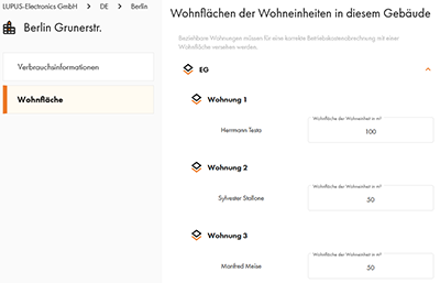
- Hinterlegen Sie Ihre Kontoverbindung, damit diese auf der Betriebskostenabrechnung für Ihre Mieter genutzt werden kann.
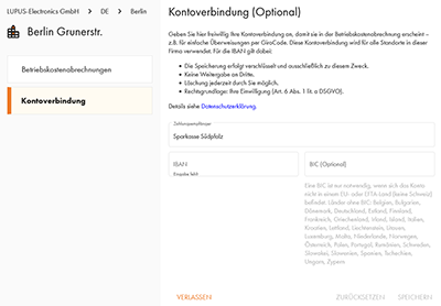
- Zum Erstellen der Betriebskostenabrechnung müssen Sie nur noch die Informationen in den folgenden Fenstern finalisieren.
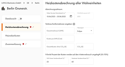
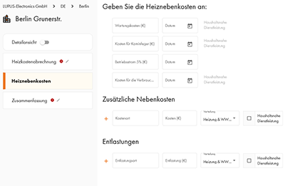
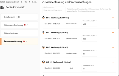
- Optional: In einer Detailansicht haben Sie noch tiefergehenden Zugriff
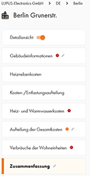
- Die Betriebskostenabrechnung wird Anhand der Messdaten und Wohnungsinformationen für jede Wohnung erstellt. Hier auch der Link zu einer Beispielabrechnung